Defect Analysis in Thermal Nanoimprint Lithography
110 likes | 367 Vues
Defect Analysis in Thermal Nanoimprint Lithography. Yoshihiko Hirai, Satoshi Yoshida, and Nobuyuki Takagi Journal of Vacuum Science & Technology B: Microelectronics and Nanometer Structures , Vol. 21, No. 6, pp. 2765–2770, November 2003 Presentation by Chris Hannemann. Overview.

Defect Analysis in Thermal Nanoimprint Lithography
E N D
Presentation Transcript
Defect Analysis in Thermal Nanoimprint Lithography Yoshihiko Hirai, Satoshi Yoshida, and Nobuyuki Takagi Journal of Vacuum Science & Technology B: Microelectronics and Nanometer Structures, Vol. 21, No. 6, pp. 2765–2770, November 2003 Presentation by Chris Hannemann
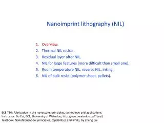
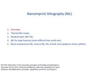
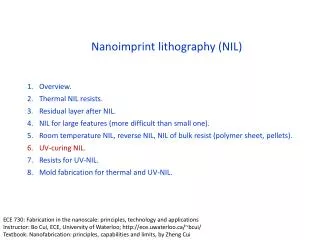
Overview • Thermal nanoimprint lithography process • Step-by-step FEA stress/strain simulations • Experiments/proposed process improvements • Conclusions
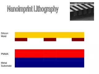
Thermal NIL • Thermoplastic polymer heated above Tg • Mold pressed and held • Temperature dropped below Tg to set polymer • Polymer ‘released’ from mold
Fracture Issues • Fracture defects occur during cooling (different thermal expansion rates) and mold release • Increased friction force in high aspect ratio features increases rate of fracture
Hot Pressing Step • Polymer treated as rubber elastic body • Polymer ‘stretched’ into cavity, though stress spreads easily due to fluidity of polymer above Tg
Cooling Step • Stress and strain concentrations near corner of feature
Release Step • Principal stress distribution during release step • Friction force pulls polymer upwards
Revised Processes Conventional Revised Advanced
Conclusions • Simulations assert that stress concentrations near corner of the pattern are formed during the cooling process and from pressure applied below Tg • Releasing pressure below Tg and slowing the cooling process help mitigate fracture defects