Download
1 / 24
240 likes | 451 Vues
Effect of spar-type floating wind turbine nacelle motions on drivetrain dynamics. Yihan Xing, CeSOS, NTNU, Trondheim Madjid Karimirad, CeSOS & Nowitech , NTNU, Trondheim Torgeir Moan, CeSOS , NTNU, Trondheim.

E N D
Effect of spar-type floating wind turbine nacelle motions on drivetrain dynamics • Yihan Xing, CeSOS, NTNU, Trondheim • Madjid Karimirad, CeSOS & Nowitech, NTNU, Trondheim • Torgeir Moan, CeSOS, NTNU, Trondheim www.cesos.ntnu.no CeSOS – Centre for Ships and Ocean Structures
Who are we? • Centre for Ships and Ocean Structures • Centre of Excellence • Hosted by the Faculty of Engineering Science and Technology in the Norwegian University of Science and Technology (NTNU – NorgesTeknisk-NaturvitenskapeligeUniversitet) • Located in Trondheim, Norway
Background • There are a lot of recent interests and large scale efforts to develop offshore wind; mostly in Europe, but also in USA. • Limited guidelines on offshore wind turbines in the IEC standards. • Drivetrain is a crucial component to study when exploiting offshore wind. Reliability is even more important offshore. • Offshore floating wind turbines are in its infancy. • We need to de-risk offshore wind turbines.
The Hywind concept • World’s first full scale floating wind turbine installed and operated by Statoil. • Installed 10 km off south-west coast of Norway. • Assembled in calmer fjord waters and then towed out to ocean. • 2.3 MW and generated 15 MWh in 2010. • Cost of NOK 400 million (~70 million USD). Picture courtesy of statoil.com Picture courtesy of old.aftenbladet.no
The GRC drivetrain • GearboxReliabilityCollaborativeproject, National Renewable Energy Laboratory • Fixed speed, stall-regulated, 750 kW WT
Gearbox topology • Conventional gearbox • 3 stage set-up for high-speed generator • 1 planetary, 2 parallel stages • 3 point support system Figure courtesy of NREL’s GRC milestone report, 2011
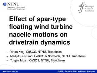
Spar floating system for GRC WT heave sway pitch yaw surge roll
Highlights of findings • Drivetrain comparison, floating spar-type WT vs. land-based WT. • Same drivetrain, but on different WT platform. • Higher main shaft loads (torque and non-torque). • Non-torque = axial, shear & bending. • Higher loads in the internal drivetrain responses. • Especially in the low speed stage. • Higher loads appear especially in the form of higher standard deviations.
Modeling methodology • Decoupled solution Global aero-hydro-servo-elastic simulation Main shaft loads Nacelle motions Drivetrain multi-body simulation
Global aero-hydro-elastic-servo simulation • Utilized HAWC2 code from Risø. • Aerodynamics – blade element momentum method with various engineering corrections. • Hydrodynamics – Morrison formula with wheeler wave stretching and separate pressure integration for buoyancy. Quasi-static force DLL for mooring line forces. • Elastic – wind turbine modeled using Timoshenko beam elements • Servo – force DLL for generator dynamics
Using MBS software to model the drivetrain • MBS = multibody simulation • We are using SIMPACK. • The drivetrain is divided into many bodies (rigid and flexible) and are interconnected using joints. Force elements and constraints can be applied between various bodies.
Drivetrain model detail • 6 DOF gears with bearing compliances • Flexible shafts Tooth contact model Bearing model
Input forces/moments and motions into drivetrain model Dummy body (in blue) where the nacelle motions are applied Forces/moments
Response variables selected for study • Main shaftloads • axial, bending, shear and torque. • Total tooth contact forces in circumferential direction. • Bearing forces. • Gear deflections (not presented here). • All results are based on 1 hour time domain simulations.
Load cases • The Statfjord site in the north sea used as a representative site. • Wind and waves are correlated.
FWT vs. WT • Compare FWT and WT responses for each load case • Butonlythe operating load cases for theinternaldrivetrainresponses. • Presented as differences as percentage vs. WT
Comparison of main shaft loading, FWT vs. WT Mean values Standard deviations • Very small increases in the mean values, with exception of mean bending moment • Big increases (>20%) in all SDs; especially shear and axial forces (note: magnitudes of axial and shear force SDs are small) Shear forces Bending moments Axial forces Torque Torque Axial forces Shear forces Bending moments
Tooth contact forces, FWT vs. WT +8% to +20% S.D. • No difference in mean tooth contact forces. • Increase in SDs; increases larger at less severe load cases. +20% S.D. at less severe load cases
Bearing loads, FWT vs. WT • INP-A:+90% to +550% axial S.D. • PLC-B: +90% to +500% axial S.D. • PL1-B: +25% to +40% axialmean, +15% to 35% axial S.D. • ~+20% radial S.D. for most bearingsrelated to LSS. Most increases occur at the low speed planetary stage.
Prominent increases in S.D. at the IMSS and HSS at less severe load cases. In the range of +~20% for bothaxial and radial S.D.
Conclusions • Designed a spar floating system for the GRC WT. • Performed global aero-hydro-servo-elastic simulations and transferred the main shaft loads and nacelle motions into a multibody drivetrain model. • Compared differences between FWT and WT in terms of the main shaft loads and internal drivetrain responses • tooth contact forces, bearing loads & gear deflections (not presented).
There are increases in SDs of the main shaft loads; particularly the non-torque loads • General increase in the internal drivetrain response variables associated with the low speed stage. • Alsoincreases at theintermediate and high speed stages at the less severe load cases.