Ceiling Radiant Cooling Panels as a Viable Distributed Parallel Sensible Cooling Technology
180 likes | 382 Vues
Ceiling Radiant Cooling Panels as a Viable Distributed Parallel Sensible Cooling Technology. Christopher L. Conroy, E.I.T. L. D. Astorino Companies, Pittsburgh PA Stanley A. Mumma, Ph.D., P.E. Penn State University, Dept. of Architectural Engineering.

Ceiling Radiant Cooling Panels as a Viable Distributed Parallel Sensible Cooling Technology
E N D
Presentation Transcript
Ceiling Radiant Cooling Panels as a Viable Distributed Parallel Sensible Cooling Technology Christopher L. Conroy, E.I.T. L. D. Astorino Companies, Pittsburgh PA Stanley A. Mumma, Ph.D., P.E. Penn State University, Dept. of Architectural Engineering Integrated with Dedicated Outdoor Air Systems
Presentation Overview • Introduction • Radiant Cooling Theory • HVAC Paradigm • Advantages • Example • Integration of Fire Suppression • Conclusions and Solutions
Radiant Cooling Panels Fan Coil Units Unitary ACs Air Handling Units Unit Ventilators Integrating Dedicated Outdoor Air Systems with Parallel Terminal Systems
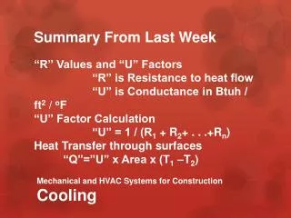
Radiant Cooling Theory • Uses both Radiation and Convection • Radiation (50-60%) • Stefan-Boltzmann Equation • qr = 0.15x10⁻⁸ · [(tp+460)4 – (ta+460)4] • Convection (40-50%) • ASHRAE S&E 1996 • qc = 0.31 · |tp- ta|0.31 · (tp- ta)
Radiant Cooling Paradigm • Expensive • High first cost • Difficult or improper installation • Unavailable • Condensation!!! • Condensation!!! • Condensation!!!
Thermally Bonded Blanketed with Insulation Aluminum or Copper Fins Copper Tubing (Serpentine or Parallel Arrangement) Radiant Cooling Panel Construction
Cost Advantages • Long Term Savings • Smaller, More Efficient Chillers • Reduced Fan Energy • Reduced Maintenance Cost • Not paying for Over Ventilating • Other Cost Savings • Piping is not insulated • Reduced Sprinkler Piping • Testing and Balancing Made Simpler $ $ $
Indoor Air Quality Advantages • High comfort levels • No condensate drains or drain pans • Meets ANSI/ASHRAE Std 62-1999 • Quick response time • Individual room control at low cost
Building Advantages • Architecturally Integratable • Silk screening available • Perforated face (acoustics) • Great for Retrofit or New Construction • Reduces Mechanical Space • Less Ductwork • Less vertical shaft space • Higher ceilings and/or reduced building heights • Simpler Coordination Between Trades • Integration of fire suppression • Less interferences (crossover ductwork)
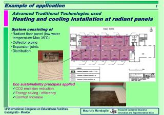
1000 ft2 78°F / 40% Example: Step 1Defining Parameters • Open Office Plan • 1000 ft2 • Define Design Conditions • 78ºF DBT / 40% RH • 7 People (20 cfm/person) • Space Loads • 7 People (Office Work) • 2 W/sq ft (Lighting) • 1 W/sq ft (Equipment) • 4,000 Btu/h (Skin Loss) • 14,000 Btu/h (Total Sensible) • 1,435 Btu/h (Total Latent)
Step 3Calculation of CRCP Capacity • Room DPT = 52°F • 78°F / 40% RH • DOAS DPT = 44°F • 1,435 Btuh Latent Load • 140 cfm @ 55°F • 3,500 Btuh Sensible Load • Panel tfi = 55°F • Panel Temp = 60°F • Qs = 29.7 Btuh/ft2 • 10,500 Btuh • 354 ft2 of panel
Step 4Selection and Layout of CRCP • 126 4x2 Ceiling Panels • ~ 1000 ft2 • 24 Light Fixtures • ~ 20% of Ceiling • 49 Ceiling Radiant Cooling Panels • 392 ft2 (40%) • 400 sq. ft. Leftover • Diffusers • Sprinklers • Qs = 26.7 Btuh/ft2 • Room RH = 43% • Increase DOAS DPT
Step 5Compare Acoustical Performance of CRCP Acoustical Ceiling Vs CRCP Reverberation Time (sec) Frequency (Hz)
T Chilled Water Loop COMPRESSION TANK MAKE-UP PUMP CRCP’s ZONE VALVES SECONDARY PUMP (VFD)
ALARM VALVE CHECK VALVE FIRE PUMP ASSEMBLY FIRE FLOW SWITCH Integrated Fire Suppression System
Seen the Advantages Concluded that CRCP’s can be Used Safely with No Condensation Problems Defined a Simple Selection Process Examined the Opportunity for Fire Suppression Integration Break the HVAC Paradigm More Successful Applications Spreading the Word Explore the Possibilities of Lowering Cost Increase Availability Research a way to produce custom lengths on site Development Through the Solar Industry Conclusions and Solutions
Questions $ $