
Chapter 2: Combinational Logic Circuit (Part2)
E N D
Presentation Transcript
EET107/3DIGITAL ELECTRONICS 1 Chapter 2: Combinational Logic Circuit (Part2)
2.2 Converters Comparators Decoders Encoders Code converters
Comparator • To compare the values of two binary strings (or binary words) to determine if they are exactly equal, greater than or less than. • Truth table for a comparator: What is the Boolean expression for this truth table? Can you draw the circuit for basic comparator?
Comparator • Comparing two binary strings (or binary words) to determine if they are exactly equal. • Truth table for a comparator: A B A=B 0 0 1 0 1 0 1 0 0 1 1 1 A=B is same as output for Ex-NOR gate
Comparator • Example:Determine the A=B, A>B, and A<B outputs for the input numbers shown on the comparator as below: • The number on the A inputs is 01102=610 and the number on the B inputs is 00112=310 . Therefore, the A>B output is HIGH and the other outputs are LOW
Another example, to design a comparator to evaluate two 4 bit numbers, we need 4 Ex-NORs and a 4 input AND gates 8 bit magnitude comparator: Comparator
Encoder • Encoder converts information such as decimal number or an alphabetical character into some binary coded form • Encoder is usually used for: • Data representation • Data security • Data compression
Encoder • Example: 8-to-3 Binary Encoder
Encoder Design a Decimal-to-BCD Encoder. • Come out a truth table (input / output) • From truth table, get an equation for each output • Draw a circuit for basic decimal-to-BCD encoder base on output equation. Note : Do not forgot to label LSB & MSB • How many inputs? • 10 ( 0 – 9 ) • How many outputs? • 4 (because we need 4 bits to express 9 (1001)) • How many Boolean expression? • 4 (since there are 4 outputs)
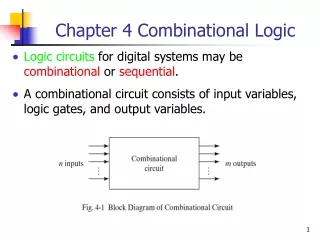
Decoder • A decoder is a circuit that creates an output based on the binary states of a given input • Do the opposite of encoder
Decoder Example: 3 to 8 Binary Decoder
/Bl D C B A a b c d e f g 0 x x x x 0 0 0 0 0 0 0 1 0 0 0 0 1 1 1 1 1 1 0 1 0 0 0 1 0 1 1 0 0 0 0 1 0 0 1 0 1 1 0 1 1 0 1 1 0 0 1 1 1 1 1 1 0 0 1 1 0 1 0 0 0 1 1 0 0 1 1 1 0 1 0 1 1 0 1 1 0 1 1 1 0 1 1 0 0 0 1 1 1 1 1 1 0 1 1 1 1 1 1 0 0 0 0 1 1 0 0 0 1 1 1 1 1 1 1 1 1 0 0 1 1 1 1 0 0 1 1 1 1 0 1 0 0 0 0 1 1 0 1 1 1 0 1 1 0 0 1 1 0 0 1 1 1 1 0 0 0 1 0 0 0 1 1 1 1 1 0 1 1 0 0 1 0 1 1 1 1 1 1 0 0 0 0 1 1 1 1 1 1 1 1 1 0 0 0 0 0 0 0 -- don’t care inputs -- Decoder Example:Seven Segment Decoder • A seven segment decoder has 4-bit BCD input and the seven segment display code as its output • In minimizing the circuits for the segment outputs all non-decimal input combinations (1010, 1011, 1100,1101, 1110, 1111) are taken as don’t-cares
Decoder • Application Example:
Code Converters • Device that converts one type of binary representation to another • Example: BCD to binary and binary to Gray code. • To convert binary to Gray code or Gray code to binary, we use X-OR gates. How???