Download
1 / 16
160 likes | 338 Vues
Radiation-Hard/High-Speed Data Transmission Using Optical Links. Richard Kass The Ohio State University. W. Fernando, K.K. Gan, A. Law, H.P. Kagan, R.D. Kass, J. Moore, D. S. Smith The Ohio State University. OUTLINE Introduction-ATLAS/Pixel Detector/SuperLHC System Architecture-issues

E N D
Radiation-Hard/High-Speed Data Transmission Using Optical Links Richard Kass The Ohio State University W. Fernando, K.K. Gan, A. Law, H.P. Kagan, R.D. Kass, J. Moore, D. S. Smith The Ohio State University OUTLINE Introduction-ATLAS/Pixel Detector/SuperLHC System Architecture-issues 0.13 μm opto-chip prototype Summary
~1.85m The Current ATLAS Pixel Detector ATLAS is a detector at CERN designed to study 14 TeV pp collisions Detector upgrade planned for Super-LHC in 2016 Pixel Detector: ATLAS’s Inner most charged particle tracker Measures (x,y,z) to ~30 mm Pixel detector is based on silicon Pixel size 50mm by 400 mm ~80 million pixels Radiation hardness is an issue must last ~ 10 years A pixel module contains: 1 sensor (2x6cm) ~40000 pixels 16 front end (FE) chips 2x8 array Flex-hybrid 1 module control chip (MCC) There are ~1744 modules
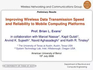
Present Pixel Opto-link Architecture Current optical link of pixel detector transmits signals at 80 Mb/s Opto-link separated from FE modules by ~1m transmit control & data signals (LVDS) to/from modules on micro twisted pairs Use PIN/VCSEL arrays Use 8 m of rad-hard/low-bandwidth SIMM fiber fusion spliced to 70 m rad-tolerant/medium-bandwidth GRIN fiber a Simplify opto-board and FE module production a Sensitive optical components see lower radiation level than modules a PIN/VCSEL arrays allow use of robust ribbon fiber ~80m ~1m optoboard VCSEL:Vertical Cavity Surface Emitting Laser diode VDC:VCSEL Driver Circuit PIN:PiNdiode DORIC:Digital Optical Receiver Integrated Circuit optoboard holds VCSELs, VDCs, PINS
SLHC Pixel Opto-link Architecture published in: NIM A 555 (2005) DORIC VCSEL Pin array VDC Housing 2cm Opto-pack Present Proposed
R&D Issues for Super-LHC Radiation hardness of all components PIN array VCSEL arrays Opto-board ASICs: VDC, Receiver (replace DORIC) SI (PIN) @ SLHC (3000fb-1) 1.5 x 10¹⁵ 1-MeV neq/cm2 2.6 x 10¹⁵ p/cm2 or “69 Mrad” for 24 GeV protons GaAs (VCSEL) @ SLHC (3000fb-1) 8.2 x 10¹⁵ 1-MeV neq/cm2 1.6 x 10¹⁵ p/cm2 or “34 Mrad” for 24 GeV protons Increased speed of components Receiver: 160Mb/s or 320Mb/s VDC: 3.2Gb/s Clock multiplier: generates fast clock for 3.2Gb/s serializer
Opto-Chip Prototype Designed with 0.13μm process 640 Mb/s VCSEL Driver 3.2 Gb/s VCSEL Driver 640 MHz clock multipliers (4 x 160 and 16 x 40 MHz) PIN receiver/decoder (40, 160, 320 MHz) 1.5 mm x 2.6 mm
Testing the 0.13um Opto-Chips Chips were tested in our lab at OSU Chips were irradiated to SLHC dose at CERN Use CERN’sT-7 beamline, 24 GeV protons to test: • 8 VDCs 4 “Slow” & 4 “Fast” • 4 Clock Multipliers • 4 Purely Electrical Receivers • 4 Receivers + 4 Si PIN (Taiwan) • Due to limitations in the cabling could only operate DORIC/VDC at 40Mb/s • Designed special card to allow testing of PLL at 640MHz
VDC: VCSEL Driver Chip Fast VDC 3.2 Gb/s Slow VDC 640 Mb/s Fast VDC 1 Gb/s 2.5Gb/s VCSEL+macro-package not optimal Both blocks (fast/slow) work in preliminary study BER < 10-13 at 3.2 GB/s driving Optowell VCSEL LVDS-like receiver works at high speed (3.2Gb/s) Need detailed study with smaller/no package PLCC package
VDC Irradiation results VDC driving 25Ω with constant Iset and 40MHz input signal power supply Fast VDC Slow VDC bright dim Decrease in drive current can be compensated by increase in Iset
Receiver PIN Receiver/Decoder Chip Properly decodes 40, 80, & 160 Mb/s BPM signals recovered clock jitter < 250/100/50 ps for 40/80/160 MHz (<1%) LVDS-like output has good amplitude and baseline Amplitude 475mV, baseline=0.625V rise/fall time 125 ps No significant degradation after irradiation to SLHC dose 40 Mb/s BER threshold for 1 bit error/s supply current @1.5V Peak to Peak thresholds BER Threshold
Clock Multiplier Need to multiply recovered clock 160MHz/40MHz up to 640MHz for serialization. Both 4x and 16x clock multipliers work Low Clock jitter < 8 ps (0.5%) No change in current consumption after irradiation BUT: Two of the four chips lost lock during irradiation & needed power cycling to resume operation at 640 MHz Could not reproduce this behavior at OSU on test bench
Summary JFirst 0.13μm chip submission mostly successful JFull characterization of pre/post irradiation in progress Waiting for the chips to “cool off” so they can be shipped from CERN to OSU JAim for next chip submission in winter 2009 Will irradiate the chips at CERN, summer 2009
Setup for Irradiation in Shuttle at CERN 25 meter optical fiber Rad hard optical fibers Opto-boards CERN T7 Remotely moves in/out of beam CERN T7
Opto-board clock PIN DORIC data VDC VCSEL VCSEL VDC Real Time Monitoring in T7 Beam Test Compare transmitted and decoded data measure minimum PIN current for no bit errors Measure optical power Signal routed back to opto-baord via test board attached to 80-pin connector & test board Real time testing of opto-board system using loop-back setup 25m optical fiber cable bi-phase marked optical signal Opto-Chip setup decoded data decoded clock In beam In control room Bit error test setup at CERN’sT-7 beamline 24 GeV protons Two VCSEL arrays from same vendor per opto-board