Download
1 / 17
290 likes | 682 Vues
ROTOR ANGULAR POSITION AND SPEED ESTIMATION WITH USE OF ELECTROMAGNETIC RESOLVERS FOR MOTOR DRIVES. Drazen Dujic LJMU, School of Engineering Electric machines and drives research group Liverpool, UK. GARS 2006. MOTIVATION.

E N D
ROTOR ANGULAR POSITION AND SPEED ESTIMATION WITH USE OF ELECTROMAGNETIC RESOLVERS FOR MOTOR DRIVES Drazen Dujic LJMU, School of Engineering Electric machines and drives research group Liverpool, UK GARS 2006
MOTIVATION • Implementation of DSP based high performance Permanent Magnet Synchronous Motor drive. • Rotor angular position and speed estimation with use of electromagnetic resolver. • Implementation of software Resolver-To-Digital (RDC) converter. GARS 2006
OBJECTIVES • Characteristics of electromagnetic resolvers. • Methods for rotor angular position estimation with use of electromagnetic resolver. • Comparison of trigonometric and observer method approach. • Hardware and software implementation. • Comparison of experimental results. GARS 2006
PRESENTATION OUTLINE • High performance motor drives. • Position and speed sensors used in motor drives. • Structure of vector controlled PMSM drive. • Principle of work of an electromagnetic resolver. • Angle measurement with trigonometric method. • Angle measurement with observer method. • Implementation. GARS 2006
HIGH PERFORMANCE DRIVES • Start-stop operation. • Fast and precise response. • Trajectory tracking. GARS 2006
POSITION / SPEED SENSORS GARS 2006
ω* + Iq* Vq PWMa Vα d, q α, β 3-phase VSI SVPWM Σ PI Σ PI PWMb – – Vd Id*=0 PWMc Vβ Σ PI ωr – θr Iq Iα Ia d, q α, β α, β a, b, c Ib Id Iβ Ic θr Speed Calculation resolver PMSM PMSM VECTOR CONTROLLED DRIVE GARS 2006
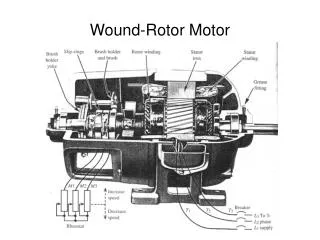
ELECTROMAGNETIC RESOLVER • Hybrid construction - rotating transformer. • Robust and environmental insensitive. • Require excitation signal (carrier). • Sine wave, few kHz • Output signals = sine & cosine signals modulated by carrier. GARS 2006
METHOD 1 - TRIGONOMETRIC • Simple concept. • Sensitive to noise. • Accuracy depends from software implementations. • Division and Arc Tan is not trivial to implement. • Round off errors. • Lack of information about speed of rotor. GARS 2006
METHOD 2 - ANGLE-TRACKING OBSERVER • Smoothing capability. • PI reg. and closed unity feedback loop. • Adjustable dynamics • Damping factor. • Natural frequency. • Less sensitive to noise. • Complicated software implementation. • Information about speed. GARS 2006
OBSERVER- parameter tuning • AIM - Investigation of influence of observer parameters on the SETTLING TIME and PEAK OVERSHOOT. GARS 2006
EXPERIMENTAL SET-UP • Three-phase PMSM • Three-phase induction motor as load • Three-phase voltage source inverter • Analog Device ADMC401 processor • Resolver and encoder mounted on motor shafts • 10kHz SVPWM • Field Oriented Control of PMSM GARS 2006
HARDWARE GARS 2006
HARDWARE GARS 2006
EXPERIMENTAL RESULTS 1500 rpm observer GARS 2006
CONCLUSIONS • Software RDC implementation is presented. • Few additional electronics component necessary. • Low cost. • Good bandwidth characteristics. • Problems with speed estimation using trigonometric approach. • Improved observer schemes. GARS 2006
Thank you for your attention GARS 2006