Download
1 / 19
260 likes | 686 Vues
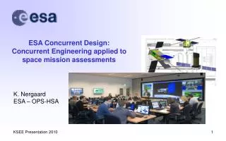
ESA Concurrent Design: Concurrent Engineering applied to space mission assessments. K. Nergaard ESA – OPS-HSA. ESA FACTS AND FIGURES. Over 30 years of experience 18 Member States Five establishments, about 2000 staff 3 600 million Euro budget (2009) Over 60 satellites designed and tested

E N D
ESA Concurrent Design: Concurrent Engineering applied to space mission assessments K. Nergaard ESA – OPS-HSA
ESA FACTS AND FIGURES • Over 30 years of experience • 18 Member States • Five establishments, about 2000 staff • 3 600 million Euro budget (2009) • Over 60 satellites designed and tested • More than 10 scientific satellites in operation • Five types of launcher developed • Over 180 launches made
ESA Member States • Austria, Belgium, Czech Republic, Denmark, Finland, France, Germany, Greece, Ireland, Italy, Luxembourg, Norway, the Netherlands, Portugal, Spain, Sweden, Switzerland and the United Kingdom. • Canada takes part in some projects under a Cooperation Agreement. • Hungary, Romania and Poland are European Cooperating States. • Cyprus, Slovenia, Estonia and Latvia have recently signed Cooperation Agreements with ESA.
The ESA project life-cycle = CDF application / quantity = CDF application / quantity I n d u s t r y Evolving Applications Evolving Applications Phase C/D Phase A Phase B … E S A Launch Pre Pre - - … Review Review SPEC. SPEC. ’ ’ s s SPEC. SPEC. ’ ’ s s Review Review SPEC. SPEC. ’ ’ s s CDR CDR FDIR FDIR Ph. A Ph. A 2 1 12 12 3 2 20 20 100+ 100+ Lessons Learned Lessons Learned
Why do we need Concurrent Engineering? Sequential Design (“over-the-fence” approach) • To overcome the communication gaps between the “designer” (who produces design information) and the “user” (who utilises the design information)
Possible approaches to system design Concurrent design Centralised design
The Concurrent Design Facility (CDF): what is it? • The ESA Concurrent Design Facility is an Integrated Design Environment (IDE)available to all ESA programmes for interdisciplinary and inter-directorate applications, based on Concurrent Engineering methodology • the implementation started in Nov.1998, on an experimental basis with initiative (and support) of the General Studies Programme (GSP) • initially conceived for the assessment and the conceptual design of future space missions, i.e. internal pre-phase A / feasibility studies • the main ESA CDF is in ESTEC with other establishments having satellite CDF systems (such as ESOC) • featuring: • team orientated concurrent engineering • integration of tools, project data, mission and system models • simultaneous participation of all mission domains, incl. Programmatics/AIV, Operations, Cost Engineering, Risk Analysis, CAD, Simulation
Technical Domains Domain Specialists EngineeringTools & DB‘s Interfacing Group Data Sharing Team Engineers System Perspective Integrated Design Environment CDF: the approach (Organisation dependent) • Re-organization of existing tools and human resources in a more effective (i.e. “concurrent”) way
CDF: the achievements Activities performed • 100+ (potential) future missions studied and designed internally at pre-Phase A, conceptual, system level • 4 new launcher concept design • 11 complex payload instrument design (IDA), incl. Platform, system, mission • 18 reviews of Industrial Phase A studies (internal + Industry) and Phase B • 5 ISS on-board facilities/experiments accommodation studies; teaming with/supporting Industry in Phase A • Joint studies with NASA/JPL/PDC-Team X (Distributed Concurrent Engineering), CNES CIC, DLR, Industry, Academia • Anomaly investigation for later project phases • Educational, training, promotion and standardisation activities Spin-off • Transfer of CDF know-how and software tonational Agencies, Industry, Academia
Benefits • Performances(typical pre-Phase A study): • Study duration (Design phase): 3-6 weeks (“classical” 6-9 months!) • Factor 4 reduction in time • Factor 2 reduction in cost (for the Customer) • Increased number of studies per year, compatibly with max 2 parallel studies • Improvement in quality, providing quick, consistent and complete mission design, incl. technical feasibility, programmatics, risk, cost • Technical report becomes part of the specs for subsequent industrial activity, Cost report remains the ESA independent reference • Capitalisation of corporate knowledge for further reusability • CDF: an essential tool for the ESA Decision Making and Risk Management processes
Process elements • Conducted in sessions • plenary meeting where representatives of all space engineering domains participate from early phases (requirement analysis) to end of design (costing) • 6 to 10 session / study, 4 hour / session, bi-weekly frequency • team leader co-ordination • customer participation • Model driven • On-line design • Highly co-operative & interactive • Iterations • Design options comparison and trade-offs
Design process Mission requirements & constraints Software Study results Attitude determination & control Instruments Objectives Data handling Environment S/C Design Lifetime Telemetry tracking & command S/C Configuration Electrical power Payload Launcher Reliability Mission analysis Risk Schedule Thermal control Cost Technology Operations & ground systems Dry mass Simulation Budget Programmatics Propulsion Study requirements Options Wet mass Products Structure Conceptual model of mission & spacecraft design process Study Level Propellant mass Planning Launch mass Adapter Resources
CE: iterative process The Spiral Model Mission analysis Mission requirements analysis Sub-system design Design verification Cost analysis Risk assessment Key Parameters
CDF: the team • Team of ESA specialists (senior and junior!) • Technical disciplines (‘CDFpositions’) selected for Phase 0 studies (according to ESA organisation): Systems Power Instruments Command and Data Handling Mission analysis Communications Propulsion Ground Systems & Operations Attitude and Orbit Control Simulation Structures/ConfigurationProgrammatics Mechanisms/Pyros Risk Assessment Thermal Cost Analysis Black: sub-system level Blue: system level Red: based on hi-end tools Note: Instrument design activities have specialised teams with disciplines such as Receiver, Optics etc.
Payload &P/L accommodation Advanced launchers Crewed vehiclesfor explorationpreparation programme Diverse range of space missions Socrates S5P ROSITA instrument on Columbus External Platform Heavy Lift Launch Vehicle ExoMars Human Missions to Mars Telescopes and Technology FIRI Moon Lander ISS Internal Payload – Science Requirements Definition IMPACT facility inside an ISS rack WiFLY Laplace
New CDF application - System of Systems architecture Service oriented – Example: GIANUS • Architecture and integration of independent space assets and systems to provide a layer of global services (e.g. security) • Collaboration among ESA programme directorates and other Agencies • Support EU and national authorities dealing with Civil Crisis Management (ref. EC-EDA-ESA workshop - 16 Sep. 2009 - on Space for Security and Defence)