Monitoring & Feedback Control
Monitoring & Feedback Control. Monitoring & Feedback. Learning Activities View Slides; Read Notes, Listen to lecture Do on-line workbook. Lesson Objectives When you finish this lesson you will understand: Monitoring and control of power circuits Review of sensor techniques

Monitoring & Feedback Control
E N D
Presentation Transcript
Monitoring & Feedback • Learning Activities • View Slides; • Read Notes, • Listen to lecture • Do on-line workbook • Lesson Objectives • When you finish this lesson you will understand: • Monitoring and control of power circuits • Review of sensor techniques • Sensing for weld quality Keywords Monitoring, Feedback Control, Force Gage, Piezoelectric Gage, Voltage, Manganen Shunt, Meter Calibration, Rogowski Coil, Hall Effect Transducer, Power Factor Monitoring, Automatic Voltage Control, Current Regulation, Constant Current, Nugget Expansion, Optical Fringe Sensor, Dynamic Resistance, Dynamic Power Factor, Current Stepper, Acoustic Emission, Ultrasonic, Direct Temperature, Infrared
Sensors for Monitoring • Control of Welder • Control of Weld Quality
Electrode Electrode Force Gage
Secondary Current Shunts • Must have geometry - no skin effect HF problems • Return Conductors not Couple with Magnetic Field • Sometime high weight for robotics • Not completely secondary impedance non-intrusive
Meter Calibration
Can not use: IRMS = 0.707 Ipeak Androvich “Resistance Welding Constant Current Heat Control”, AWS Sheet Metal ConfV, 1992
Non-ferromagnetic Material In Core No Saturation
X-Ray Bowling, DeLeon, Pietsch, Senior Project report, 1999
Rogowski Coils Are: • Extremely Amplitude-Linear Devices • Not Frequency Sensitive (good Coils have 8 Octaves) • Position Sensitive (Coil Winding Imperfections) • Sensitive to Return Conductor Position
Hall Effect Devices Are: • Very Position Sensitive • Temperature Sensitive • Proportional to Current not Rate of Change • Can Use on 3 phase • Sensitive to Location of Return Conductors
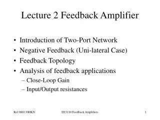
Power Factor: Current Through &Voltage Across Primary
Control of Welder • Automatic Voltage Control (AVC) • Current Regulation • Constant Current
Androvich “Resistance Welding Constant Current Heat Control”, AWS Sheet Metal ConfV, 1992
AVC Heat Control (constant voltage) Compensates for primary voltage changes Act. % Avail Current = [Act. Volt/Set Volt] x Programmed % Current • AVC: • Holds Prim & Sec Voltage Constant on a 1/2 cycle basis • Changes total available current based on voltage changes • Does not compensate correctly for change in sec Resistance or Impedance • Usually has current pick up coil to alarm problems Androvich “Resistance Welding Constant Current Heat Control”, AWS Sheet Metal ConfV, 1992
Current Regulation Heat Control • Current Regulation: • Uses Current Pick-up Coil & Analog Feedback Circuit • Requires variable gain, reset, dead band, that effect current output • Normally requires 3 to 5 cycles to stabilize • Therefore, used mostly with seam welding not spot welding Androvich “Resistance Welding Constant Current Heat Control”, AWS Sheet Metal ConfV, 1992
Constant Current Heat Control Program Controller Directly in Secondary Amperes, then controller holds secondary current within +/- 1% • Controller Needs to Perform: • Digital Sampling of Primary and Secondary Current or Use Turns Ratio to Calculate Secondary • Calculate RMS Current on 1/2 cycle basis • Respond to process changes on 1/2 cycle basis (Use Predictive Feedback) • Self teach relationship between current and % available current • Primary benefit is its ability to compensate for changes in secondary impedance Androvich “Resistance Welding Constant Current Heat Control”, AWS Sheet Metal ConfV, 1992
Predictive Feedback • Use Large Firing Angle (small current) for first 1/2 cycle • Read results of current • Calculate a ratio between % available current and actual • Predict where to fire the next 1/2 cycle using tables
Androvich “Resistance Welding Constant Current Heat Control”, AWS Sheet Metal ConfV, 1992
Lower Resistance Note: an increase in primary voltage is required to overcome the increase in secondary resistance Longer Fire Angle Higher Resistance Shorter Fire Angle Androvich “Resistance Welding Constant Current Heat Control”, AWS Sheet Metal ConfV, 1992
Benefit Extends to Seam Welding Also Longitudinal Seam welders have large, deep secondary , and inductance changes as more ferromagnetic material goes into throat. Circumferential seam welders have short, small secondary with constant inductance Constant Current Adjusts Cuff, Seam Welding with Constant Current Controls Welding Journal, Sept 1998
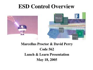
Tsai, Experimental Study of Weld Nugget Expan, Paper B1, Sheet Metal Welding Conf V, AWS, 1992
4 Cycle 12 Cycle 6 Cycle 14 Cycle 16 Cycle 8 Cycle 22 Cycle 10 Cycle Tsai, Experimental Study of Weld Nugget Expan, Paper B1, Sheet Metal Welding Conf V, AWS, 1992
9.8 ka 12.2 ka 10.8 ka 13.8 ka 14.0 ka Tsai, Experimental Study of Weld Nugget Expan, Paper B1, Sheet Metal Welding Conf V, AWS, 1992
Real Time Equipment Arrangement Power Supply Strain Gage Signal Conditioner Oscilloscope Voltage Leads Print Displacement Transducer Isolation Box Data Recorder Tap Integration
V Current Voltage Two Points per Cycle (+ & - 1/2 cycles)
Liang, “Fundamental Study of Contact Behavior in RSW” OSU Dissertation, 2000
Dickinson, Welding in Auto Industry, AISI, 1981
Dickinson, Characterization of Spot Weld..” Welding Journal, 1980
Dickinson, Welding in Auto Industry, AISI, 1981
Expulsion • Interfacial Expulsion • Excessive Current • Excessive Time • Surface Expulsion • Excessive Current • Low Force • Dirty Material • Poor Fit-up • Worn Electrodes
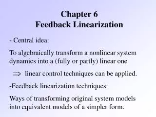
Dynamic Power Factor Monitoring Power Factor = Cos = 100% if pure Resistive = 0% if pure Reactive Reactance is basically fixed; Changes only if size or shape of secondary changes So Dynamic Changes in Resistance Result in Dynamic PF Changes
Power Factor Can Be Measured at Controller, No Wires at Electrode Needed } } = Negative Half Cycle + = Positive Half Cycle Count # of Expulsions Per 25 Welds Boilard, “Automatic Current Steppers for Improved Weld Quality” AWS Sheet Metal Welding Conf. V, 1992
Automatic Current Stepper Based on Dynamic Power Factor If 5 Expulsions/25 Welds Current Decrease 1% If No Expulsion Current Increase 1%
Havens “Controllin Spot Welding Quality and Expulsion” SME Paper AD76-279 1976
Havens “Controllin Spot Welding Quality and Expulsion” SME Paper AD76-279 1976