UML
UML. OVERVIEW OF UML :- We need a Modeling Language! We will use the Unified Modeling Language, UML), Provides a standard for artifacts produced during development – (semantic models, syntactic notation, and diagrams: the things that must understood, controlled, and exchanged.

UML
E N D
Presentation Transcript
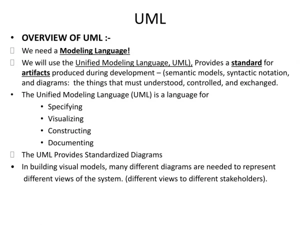
UML • OVERVIEW OF UML :- • We need a Modeling Language! • We will use the Unified Modeling Language, UML), Provides a standard for artifacts produced during development – (semantic models, syntactic notation, and diagrams: the things that must understood, controlled, and exchanged. • The Unified Modeling Language (UML) is a language for • Specifying • Visualizing • Constructing • Documenting • The UML Provides Standardized Diagrams • In building visual models, many different diagrams are needed to represent different views of the system. (different views to different stakeholders).
SCOPE OF UML • UML is a language for • Specifying • Visualizing • Constructing • Documenting • UML is a language:- • Language provide vocabulary & rule for combining words for communication. • Modeling language is a lang. which focus on conceptual & physical representation of a system • Standard language for s/w blueprint • Tell how to create real well formed models. • UML is a language for Visualizing • Each symbol in UML is a well-defined semantics • UML is a language for Specifying • Building model that are precise, unambiguous, & complete • It address specification of all important analysis ,design & implementation
UML is a language for constructing • it’s model can directly connected to a variety of programming language such as java,c,c++ etc • Mapping permit forward engg: generation of code from a UML model into a programming language. Reverse also possible • UML is a language for documenting • Artifact include:- • Requirement - source code - prototypes • Architecture - project plans - release • Design - tests • It express requirements, activities ,planning & release management
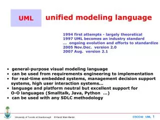
~ U Unified: • Unification of earlier object-oriented analysis and design methods. • Same concepts and notation for different application domains and different development processes. • Same concepts and notation through the whole development lifecycle. ~ M • Modeling: • Making a semantically* complete abstraction of a system.(* The formal specification of the meaning and behavior of something) L ~ • Language: • A graphical language
State Diagrams State Diagrams Class Diagrams Use-Case Diagrams Use-Case Diagrams State Diagrams Use-Case Diagrams State Diagrams Use-Case Diagrams Object Diagrams Use-Case Diagrams Activity Diagrams Scenario Diagrams State Diagrams Scenario Diagrams State Diagrams State Diagrams Sequence Diagrams Models Component Diagrams Scenario Diagrams Component Diagrams Scenario Diagrams Component Diagrams Deployment Diagrams Collaboration Diagrams
Some of the UML Goals • Define an easy-to-learn but semantically richvisual modeling language. • Unify ideas from other modeling languages and incorporate industry best practices. • Support higher-level development concepts such as collaborations (design patterns), frameworks and components. • Provide flexibility for applying different processes and mapping to different programming languages. • Support extensibility and specialization mechanisms so that the core concepts can be extended. • Provide a formal basis so that model interchange between different OO tools will be possible.
The Value of UML • Open standard. • Supported by many tools. • Supports the entire development lifecycle. • Support diverse application areas. • Based on experience and needs of the user community.
UML Is Not a Visual Programming Language • UML is a visual modeling language. It does not have all necessary visual and semantic support to replace programming languages. • But UML has a tight mapping to a family of OO languages like C++ and Java.
UML Is Not a Development Process A development process defines: - Who is doing What, - When to do it, and - How to reach a certain goal • The UML is intentionally process independent, and defining a standard process was not a goal of UML. Different domain may require different processes. • But the UML authors promote a development process that is use-case-driven, architecture centric, iterative and incremental. (Example of method: RUP)
UML 2.0 New Features • Goal:- - provide user with ready-to-use expressive visual modeling language • Support higher level development concept ,such as collaboration,framework, pattern, component • New diagram include:- • Structure diagram • Composite diagram • Communication diagram • Timing diagram • Interaction overview diagram
Significant changes in 2.0 • Activity diagrams completely overhauled – OMG realized they were being used for business modeling instead of class modeling. Diagrams were made more similar to flowcharts. • Package Diagrams added for high level overview of code structure. • Collaboration diagrams renamed as communication diagrams but specification remains the same. • Timing diagrams added for real-time applications.
DIAGRAM STRUCTURE DIAGRAM STRUCTURAL BEHAVIORAL STRUCTURAL DIAGRAM PACKAGE DIAGRAM OBJECT DIAGRAM CLASS DIAGRAM DEPLOYMENT DIAGRAM COMPONENT DIAGRAM COMPOSITEDIAGRAM
Behavioral DIAGRAM • Behavioral diagram ACTIVITY DIAGRAM INTERACTION DIAGRAM USE-CASE DIAGRAM STATE MACHINE DIAGRAM INTERACTION OVERVIEW DIAGRAM TIMING DIAGRAM COMMUNICATIONDIAGRAM SEQUENCE DIAGRAM
MAJOR COMPONENT IN UML 2.0 • New concept for describing internal architecture & collaboration by mean of port, connector & part • Introduction of inheritance of behavior in state machine & encapsulation of sub machine through use of entry & exit point • Improve encapsulation of component through complex parts with protocol state machine that control interaction with environment • Improvement of specification, realization & wiring aspect of component • Interaction of action & activities & use of flow semantics instead of state machine • Interaction improved by composition,reference,exception ,loop etc
Composite state • Difficult to specify composite state that can be reused in other state machine • UML 2.0 introduces exit & entry point that control access to a composite state
ARCHITECTURAL CONCEPTS IN UML • Core concept of describing internal structure are part, connector, port • PARTS:- • Describe internal structure of a class • Part lives &dies as part of lifetime of an object of containing class 2. PORTS:- • Port describe interaction point for a class,it is addressiablei.e signal can be send to it • Port has interfaces that specifies operation & signal offered by class • Class can send & receive signal via port
CONNECTOR:- • It specifies a link that enables communication between two or more parts • It specify link between parts only • It may attached to port on directly to part • Fig. shows engine e:engine in a class car is connected by axle connector to instances in rear:wheel
STATE MACHINE IN UML 2.0 • Major changes in UML 2.0 • Composite state with entry/exit points • State machine generalization that enables inheritance & specification of behavior
OVERVIEW OF ALL UML 2.0 DIAGRAMS • 3 classification of all UML 2.0 diagrams • Behavioral diagram:- • Include activity,state,use-case,interaction diagram 2. Interaction diagram:- • communication, Interaction overview, sequence & timing diagram 3. Structure diagram:- • Class , object ,composite,component,deployment, package diagram • Activity Diagram • illustrate the dynamic view of a system. • Activity diagrams are especially important in modeling the function of a system. • emphasize the flow of control among objects.
Class diagram • shows a set of classes, interfaces, and collaborations and their relationships. • static design view of a system. • Communication Diagram - Show instance of classes ,their relationship & message flow between them • Focus on structural organization ,send & receive message • known as collaboration diagram
Component diagram • Component ,their relationship & interfaces are depicted • Composite diagram • Depict internal structural of classifier such as class, component including interaction point -
Deployment diagram • Shows execution architecture of system ,include node ,h/w or s/w execution environment • Interaction Overview Diagram • Variant of activity diagram which overview the control flow within system • Use – case diagram - Show use cases, actor & relationships
Object diagram • Package diagram • Show how model element are organized into packages as well as dependencies between packages
Sequence diagram • Model sequential logic, ordering of message between classifiers
State diagram • Describe state within object • Timing diagram - Depict change in state / condition
Rules of the UML • Like any language, the UML has a number of rules that specify what a well-formed model should look like. • A well-formed model is one that is semantically self-consistent and in harmony with all its related models. • UML has semantic rules for 1. Names :- What you can call things, relationships, and diagrams 2. Scope :- The context that gives specific meaning to a name 3. Visibility :- How those names can be seen and used by others 4. Integrity :- How things properly and consistently relate to one another 5. Execution :- What it means to run or simulate a dynamic model • software-intensive system tend to evolve and may be viewed by many stakeholders • development team to not only build models that are well-formed, but also to build models that are • Elided:- Certain elements are hidden to simplify the view • Incomplete :- Certain elements may be missing • Inconsistent :- The integrity of the model is not guaranteed
CONCEPTUAL MODEL OF UML • 3 major element • UML’s basic building block • Rule that dictate how those building block may be put together • Common mechanism apply through UML . 1. UML’s basic building block • 3 kind of building block • Things • Relationship • Diagrams • things: 4 kind • structural • Behavioral • Grouping • anotational
1. structural things :- • These are the mostly static parts of a model, representing elements that are either conceptual or physical • Class: class is a description of a set of objects that share the same attributes, operations, relationships, and semantics. • A class implements one or more interfaces. • Graphically, a class is rendered as a rectangle, usually including its name, attributes, and operations
interface :- • it is a collection of operations that specify a service of a class or component. • An interface therefore describes the externally visible behavior of that element. • defines a set of operation specifications but never a set of operation implementations • Graphically, an interface is rendered as a circle together with its name. • it is typically attached to the class or component that realizes the interface • collaboration : - defines an interaction and is a society of roles and other elements that work together to provide some cooperative behavior that's bigger than the sum of all the elements. • have structural, as well as behavioral, dimensions - represent the implementation of patterns that make up a system.
use case : • It is a description of set of sequence of actions that a system performs that yields an observable result of value to a particular actor. • A use case is used to structure the behavioral things in a model. • active class : • It is a class whose objects own one or more processes or threads and therefore can initiate control activity - Graphically, an active class is rendered just like a class, but with heavy lines, usually including its name, attributes, and operations
Component • It is a physical and replaceable part of a system that conforms to and provides the realization of a set of interfaces. • A component typically represents the physical packaging of otherwise logical elements, such as classes, interfaces, and collaborations. • Graphically, a component is rendered as a rectangle with tabs, usually including only its name • node - It is a physical element that exists at run time and represents a computational resource, generally having at least some memory and, often, processing capability. - a node is rendered as a cube, usually including only its name
2. Behavioral Things • Behavioral things are the dynamic parts of UML models. • representing behavior over time and space • interaction is a behavior that comprises a set of messages exchanged among a set of objects within a particular context to accomplish a specific purpose • state machine is a behavior that specifies the sequences of states an object or an interaction goes through during its lifetime in response to events, together with its responses to those events. 3. Grouping Things • Grouping things are the organizational parts of UML models. These are the boxes into which a model can be decomposed • package is a general-purpose mechanism for organizing elements into groups. Structural things, behavioral things, and even other grouping things may be placed in a package - Graphically, a package is rendered as a tabbed folder, usually including only its name and, sometimes, its contents
3. Annotational Things • Annotational things are the explanatory parts of UML models. These are the comments you may apply to describe, illuminate, and remark about any element in a model • Note: • note is simply a symbol for rendering constraints and comments attached to an element or a collection of elements
Relationships in the UML • four kinds of relationships in the UML: 1. Dependency 2. Association 3. Generalization 4. Realization 1. dependency is a semantic relationship between two things in which a change to one thing(the independent thing) may affect the semantics of the other thing (the dependent thing). • Graphically, a dependency is rendered as a dashed line, possibly directed, and occasionally including a label 2. association is a structural relationship that describes a set of links, a link being a connection among objects. -Aggregation is a special kind of association
3. Generalization • is a specialization/generalization relationship in which objects of the specialized element (the child) are substitutable for objects of the generalized element (the parent). • rendered as a solid line with a hollow arrowhead pointing to the parent 4. Realization • is a semantic relationship between classifiers, wherein one classifier specifies a contract that another classifier guarantees to carry out. - Graphically, a realization relationship is rendered as a cross between a generalization and a dependency relationship
Common Mechanisms in the UML 1. Specifications 2. Adornments 3. Common divisions 4. Extensibility mechanisms • Specifications • UML is more than just a graphical language. Rather, behind every part of its graphical notation . • there is a specification that provides a textual statement of the syntax and semantics of that building block. • For example, behind a class icon is a specification that provides the full set of attributes, operations (including their full signatures), and behaviors • UML's specifications provide a semantic backplane that contains all the parts of all the models of a system, each part related to one another in a consistent fashion. • The UML's diagrams are thus simply visual projections into that backplane, each diagram revealing a specific interesting aspect of the system.
2. Adornments • Most elements in the UML have a unique and direct graphical notation that provides a visual representation of the most important aspects of the element. - For example, the notation for a class is intentionally designed to be easy to draw exposes the most important aspects of a class, namely its name, attributes, and operations. • Every element in the UML's notation starts with a basic symbol, to which can be added a variety of adornments specific to that symbol.
3. Common Divisions • there is the division of class and object. A class is an abstraction; an object is one concrete manifestation of that abstraction. • In the UML, you can model classes as well as objects
4. Extensibility Mechanisms • UML provides a standard language for writing software blueprints, but it is not possible for one closed language to ever be sufficient to express all possible nuances of all models across all domains across all time • For this reason, the UML is opened-ended, making it possible for you to extend the language in controlled ways. • extensibility mechanisms include 1. Stereotypes 2. Tagged values 3. Constraints 1. Stereotypes • stereotype extends the vocabulary of the UML, allowing you to create new kinds of building blocks that are derived from existing ones but that are specific to your problem • You can make exceptions in your models like basic building blocks by marking them with an appropriate stereotype, as for the class Overflow
Tagged values - tagged value extends the properties of a UML building block, allowing you to create new information in that element's specification. For example, if you are working on a product that undergoes many releases over time, you often want to track the version and author of certain critical abstractions. Version and author are not primitive UML concepts. They can be added to any building block, such as a class, by introducing new tagged values to that building block. • class EventQueue is extended by marking its version and author explicitly.
Constraints • constraint extends the semantics of a UML building block, allowing you to add new rules or modify existing ones. For example, you might want to constrain the EventQueue class so that all additions are done in order. As Figure above shows, you can add a constraint that explicitly marks these for the operation add.
OBJECT CONSTRAINT LANGUAGE (OCL) • OCL is a sub-language of UML that allow for capturing rules & attaching them to model elements which satisfy constraint for model to describe correct or well formed • It is a declarative language for describing rules that apply to UML model • It’s a precise text lang. that provide constraints & object query expression • The Object Constraint Language (OCL) is an expression language that describes constraints on object-oriented languages and other modeling artifacts. A constraint can be seen as a restriction on a model or a system. OCL is part of Unified Modeling Language (UML) and it plays an important role in the analysis phase of the software lifecycle. • Object Constraint Language (OCL), is a formal language to express side effect-free constraints. Users of the Unified Modeling Language and other languages can use OCL to specify constraints and other expressions attached to their models.
OCL is the expression language for the Unified Modeling Language (UML). To understand OCL, the component parts of this statement should be examined. Thus, OCL has the characteristics of an expression language, a modeling language and a formal language. • A UML diagram (e.g., a class diagram) does not provide all relevant aspects of a specification • It is necessary to describe additional constraints about the objects in the model Constraints specify invariant conditions that must hold for the system being modeled • Constraints are often described in natural language and this always result in ambiguities • Traditional formal languages allow to write unambiguous constraints, but they are difficult for the average system modeler • OCL: Formal language used to express constraints, that remains easy to read and write
Object Constraint Language (OCL) • Pure expression language: expressions do not have side effect ✸ when an OCL expression is evaluated, it returns a value ✸ its evaluation cannot alter the state of the corresponding executing system ✸ an OCL expression can be used to specify a state change (e.g., in a post condition) • Not a programming language ✸ it is not possible to write program logic or flow of control in OCL ✸ cannot be used to invoke processes or activate non-query operations • Typed language: each expression has a type ✸ well-formed expressions must obey the type conformance rules of OCL ✸ each classifier defined in a UML model represents a distinct OCL type ✸ OCL includes a set of supplementary predefined types • The evaluation of an OCL expression is instantaneous ✸ the state of objects in a model cannot change during evaluation
Where to Use OCL • To specify invariants on classes and types in the class model • To specify type invariants for stereotypes • To describe pre- and post-conditions on operations and methods • To describe guards • As a navigation language • To specify constraints on operations • OCL is used to specify the well-formedness rules of the UML metamodel