Back End Downconverter
This document outlines the preliminary design review of the EOVSA Back End Downconverter, covering critical design requirements, system architecture, spurious analysis, component specifications, and assembly considerations. Key insights include the need for spurious suppression and overall Tsys targets, as well as detailed component selection criteria to optimize performance and minimize costs. The design prioritizes high packing density in rack-level modules and incorporates interfaces for efficient signal monitoring and control. This review aims to ensure reliable operation and high performance for radio frequency signal processing.

Back End Downconverter
E N D
Presentation Transcript
Back End Downconverter Wes Grammer NRAO EOVSA Preliminary Design Review
Outline • Design requirements • Block diagram and cascade analysis • Spurious analysis • Component selection • Module & rack-level packaging • Interfaces (mechanical and electronic) • Production assembly and test • Costing and schedule EOVSA Preliminary Design Review
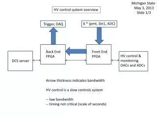
Back End Downconverter Design Requirements and Specifications • Convert selected 0.5 GHz-wide RF sub-band to baseband frequency (650 - 1150 MHz) • SMF input w/mux’d dual lin. polarizations, 1-18 GHz RF • Overall Tsys < 400K, at ambient (~298K) • Gain stability < 1%, phase stability < 1°, over TBC sec. • Baseband output power: -2 dBm, nom., both channels • Spurious and harmonic suppression: -57 dBc, min. • Monitor and control: • Serial I/O bus, RS-485 signaling, ~1.0-3.5 Mbps asynchronous transfer • 100 us max. overall latency for output level (step attenuator) control, including serial data transfer delays • Rack-mountable unit, with high packing density • Environment: Indoor, temperature control • MTBF > 15 years EOVSA Preliminary Design Review
Downconverter Module Block Diagram EOVSA Preliminary Design Review
System Cascade Analysis • Key results, after optimization: • Overall Tsys < 330K up to -50 dBm, but rises way over 400K for strongest input • Extra attenuation for signal leveling in Front End, along with high link loss make Tsys sensitive to component loss in the Downconverter, esp. in 1st IF stage. An isolator is used for a low-loss signal match before 2nd mixer. • Effect is greatly reduced by driving optical TX harder (+11 dBm). Overall Tsys is still slightly higher than spec, ~420K • Increasing 1st amp gain helps, but limited by mixer P1dB • Alternatively, extra gain can be added between the mixers, but at significant extra cost and added complexity. • 1st mixer is ~4 dB under P1dB in worst case • Higher LO drive helps, but only 2-3 dB may be available over nom. +10 dBm, because of high loss in LO distribution at 38 GHz EOVSA Preliminary Design Review
Spurious Analysis • Excel document in archive contains detailed analysis of spurious outputs and harmonics, and filter specs • Summary of key results: • Neither mixer evaluated for the 1st conversion stage has required spurious suppression, but one (Marki M9-0942) comes close at all but lowest frequencies. • Based on the RF-IF isolation of the 1st mixer, the 18 GHz LPF in the Front End need to have at least 53 dB of stopband rejection from 20-20.5 GHz. • 1st LO leakage into the signal path is most serious at 22 GHz, where the resulting spur is in the 2nd IF passband. Almost 80 dB of filter rejection is needed at this frequency in the 1st IF BPF. • 2nd IF filter needs to have 57 dB stopband rejection below 550 MHz and above 1250 MHz, to avoid distortion from aliasing EOVSA Preliminary Design Review
Component Selection Criteria • Flat frequency response, where possible • Good VSWR, where possible, to limit mismatch loss and gain ripple • Adequate P1dB in the amplifiers, to ensure good linearity • High-intercept mixers not feasible, due to high cost of required LO drive power • Mixer LO drive configuration in Downconverter is tied closely to design of LO Distribution module, to minimize total overall cost • Common bias voltages (e.g., +12V), where possible • Cost is critical: There are 30 of each Downconverter component types in the array, an expensive item can have a large impact in the overall budget. EOVSA Preliminary Design Review
Module / rack layout considerations • High-frequency paths (RF, IF1, LO1, LO2) should be as short and direct as possible, to minimize losses and added reflections. • Single component layer desired, for ease of assembly and service, and is space-efficient. Module depth limited to ~1.25” • Vertically-oriented slide-in rack modules with spaces between, to allow air flow for cooling • Assuming 19” rack width, two rows of 8 modules each, 5U or 6U high would probably work • Use shielding and filtering on digital boards, shielded cables, to limit EMI EOVSA Preliminary Design Review
Downconverter Rack Modules Conceptual Layout EOVSA Preliminary Design Review
COTS module (Schroff 6U x 8HP) EOVSA Preliminary Design Review
Downconverter Assembly Interfaces • Hardware: • (1) SC/APC SM fiber connector, signal input • (1) 2.92mm male coax adapter, 1st LO (LO1) input • (1) SMA male coax adapter, 2nd LO (LO2) input • (2) SMA male coax adapter, baseband IF outputs • (2) DB-9 or 10-pin RJ-style connectors, M&C I/O • (1) MIL-DTL-26482 connector, DC power input • Software: • Refer to table in following slide EOVSA Preliminary Design Review
Production Assembly, Testing • Production process steps • Two-port VNA measurement of amplifiers, filters, digital attenuators, couplers, mixers (port-port isolation), and optical link sets • Mechanical assembly of Downconverter • Conversion loss measurement vs. frequency of Downconverter RF chain, w/o optical RX • Verification of M&C functionality • Documentation: Test results, configuration (s/n) list EOVSA Preliminary Design Review
Component Costing, Delivery • All RF components except BPFs and 2 amplifiers have been specified, price/delivery quotes received • Good estimates or preliminary pricing on most remaining electronic components • Enclosure, connector and cable pricing are rough estimates, final TBD • Gain equalizer spec is TBD: need to characterize actual component cascade before specifying and ordering • Long lead times (over 12 weeks): • Optical links, in production quantity. Small quantity are available out of stock EOVSA Preliminary Design Review
Important Schedule Dates for Downconverter Prototypes • Have all RF components and COTS support electronics on order by end of April. • Complete mechanical CAD models and fabrication drawings by May 1, send out for quotes, begin fab in mid-May • May 1 – June 30: Design, PCB fab and component ordering for custom support electronic boards • July 1 – July 15: Order the rack(s), cables, connectors, wire, remaining components for prototype unit construction and site installation • July 1 – August 1: RF component characterization • August – September: Assemble and test 3 prototypes • October 1: Ship 3 prototypes to California for installation • Downconverter embedded firmware and test software may need to be farmed out, in the interest of saving time. This could happen during July and August, in parallel with module assembly. EOVSA Preliminary Design Review