Download
1 / 21
210 likes | 332 Vues
Outline. Summary of operational experience Powering Interlocks vs Beam Losses Dependability FMCM vs mains disturbances R2E Automated testing of interlock systems Miscellaneous Conclusions. Powering Interlocks vs Beam Interlock. LHC Devices. LHC Devices. Environmental parameters.

E N D
Outline • Summary of operational experience • Powering Interlocks vs Beam Losses • Dependability • FMCM vs mains disturbances • R2E • Automated testing of interlock systems • Miscellaneous • Conclusions
Powering Interlocks vs Beam Interlock LHC Devices LHC Devices Environmental parameters LHC Devices Movable Devices BCM Beam Loss Experimental Magnets Collimator Positions BTV screens Mirrors Timing SEQ via GMT SMP Software Interlocks CCC Operator Buttons Experiments Transverse Feedback Beam Aperture Kickers BTV Collimation System FBCM Lifetime MKI Beam Dumping System Beam Interlock System Safe Beam Flag 32 12 8 Injection BIS PIC essential + auxiliary circuits WIC FMCM Access System RF System BPM in IR6 Vacuum System BLM Timing System (PM) Access Safety Blocks RF /e-Stoppers Magnets Power Converters Doors EIS Vacuum Valves (~300) Monitors in arcs (several 1000) Monitors aperture limits (some 100) QPS (several 1000) Power Converters ~1500 AUG UPS Cryo OK • 1/4 of LHC BIS user connections for powering interlocks • , collecting a large inventory of interlock channels
A bit of statistics… Activation of BIS channels with closed BPL (~850 in total)
Dump statistics and origins for 2010 run… • This year total of 515 ‚beam dumps‘ (breaking of BPL) • 55 dumps by PIC • 23 AT INJECTION, 6 DURING RAMP, 16 AT FLAT TOP • 15 tune/orbit feedback vs QPS/PC • 12 individual circuit trips (RB.A78 VS, RQX.R2, 600A correctors due to HW failure in PC or QPS) • 11 from CRYO • 10 sector trips (QPS, nQPS) • 4 due to U_RES of Undulator • 3 electrical perturbations • 9 dumps by FMCM after mains perturbations (see later) • 1 dump by WIC in IR4 (problem with gas monitoring circuit)
Powering Interlocks vs Beam Losses… • For current intensities and setup redundancy to BLM system has worked very well (neglecting losses around IR6 due to abort gap population), ie • PIC: Apart from event in S12 (RQD.A12 not at injection), all powering events caught by PIC before any losses/orbit movement occur (including SPA and FPA in a complete sector) • Side note: Did not see a FPA in two adjacent sectors yet (e.g. AUG/UPS) • Warm magnet interlocks: Only 1 real dump provoked @ inj due to gas monitoring circuits in IR4 being switched OFF • FMCMs: No considerable losses (ie no BLM triggers) or orbit movements for any of the MPS tests or (frequent) network perturbations
Dependability • Very good experience so far, industrial as well as ‘home-made‘ electronics are exceeding reliability predictions * • No machine downtime from powering interlock systems due to component failures • In more than 3 years of commissioning/operation of ~70 systems, only 3 (transparent) interventions on redundant power supplies *Not taking into accound possible radiation effects (see later)
Dependability vs Interventions/Maintenance • Current good performance is based on a very thorough hardware commissioning campaign, where all protection related features of installed HW have been tested and validated for operation • During technical stops, interventions, etc... we exchange, upgrade, fix protection related equipment without requalifying the equipment (after exchange of power modules, QPS cards, etc..) • Currently (for me), no clear tracability of changes to protection related systems or clear guidelines/documentation for revalidation of equipment? • Point to follow up by MP3 for powering system….
FMCMs and mains disturbances • Beams dumped upon 9 occasions by FMCM following network perturbations, ie • 11-JUN-10 02.41.38 AM (400kV – all LHC) at 450GeV • 26-MAY-10 09:47:54 PM (400kV – all LHC due to thunderstorm) at 3.5 TeV • 18-MAY-10 05.35.42 AM (400kV – all LHC due to thunderstorm) at 3.5 TeV • 10-MAY-10 22.48.44 PM (400kV – all LHC) at 450GeV • 02-MAY-10 02.59.37.127000 AM (400kV - all LHC) at 450GeV • 01-MAY-10 05.50.32.127000 AM (18kV ring line, seen on dump septas) at 450GeV • 19-APR-10 05.14.30.396000 AM (400kV - all LHC) at 3.5 TeV • 07-APR-10 06.46.58.724000 AM (18kV ring line, seen on dump septas) at 450GeV • 03-APR-10 07.24.04.890000 AM (400kV - all LHC) at 3.5 TeV • All trips happened at flat top (either injection or 3.5TeV) and did not result in self-trips of power converters, apart the one on 2nd of May which tripped both RD1s, RD34s and the ALICE and LHCb dipoles (+ LHC Coll and RF equipment) • All dumps correct, as current changes exceeded specified values (decreasing thresholds will not help) • Mains perturbations seen in all circuits, but current intensities and setup do not yet induce considerable beam movements or losses, will look different later (and if happens e.g. during ramping)
03-APR-10 07.24.04.890000 AM – Fault in 400kV S phase -40kV , 30ms Courtesy of D.Arnoult Typical perturbation originating in 400kV (2 phases, V dip of ~15% for some 60ms)
Comparison to spec of “minimum immunity of equipment” • Based on the statistic of past network disturbances, a minimum immunity for equipment has been defined in an LHC ES ‘Main Parameters of LHC 400/230V Distribution System’ Voltage Swells = +50%, 10ms U nom= 400 / 230V ± 10 % Typ. Variations = ± 5 % Transients= 1200V for 0.2ms THD = 5% X X X X 03-APR-10 07.24.04.890000 AM 07-APR-10 06.46.58.724000 AM 19-APR-10 05.14.30.396000 AM 01-MAY-10 05.50.32.127000 AM Voltage Dips = -50%, 100ms
02-MAY-10 02.59.37.127000 AM – RBXWTV.L2 + others ∆I = 2A ∆I /I = 3.4 •10E-3 ∆V = 1.5V ∆V /V = 5 •10E-2 FMCM: Measured excursion > 1.5 Threshold : 0.6
19-APR-10 05.14.30.396000 AM – Trip of RD1s in IR1 an IR5 ∆I = 0.7A ∆I /I = 2 •10E-3 ∆V = 20V ∆V /V = 8 •10E-2 FMCM: Measured excursion > 8 Threshold : 0.4
19-APR-10 05.14.30.396000 AM – Perturbation on RB.A12 ∆I = 0.018A ∆I /I = 3 •10E-6 ∆V = 4V ∆V /V = 8 •10E-1
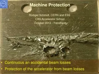
Radiation • Radiation might become an issue for industrial components of the PIC and WIC (PLCs are known to be sensitive) • New R2E studies require relocation of some PLCs • UJ56, UJ14, UJ16: Relocation of interlock equipment already prepared in 2009, might have to change depending on decision for QPS/PC equipment • US85: WIC to be relocated to UA83 (in progress , before end 2010) • TI8: WIC to be relocated upstream of collimator (in progress, before end 2010) • In-house electronics has been shown to be adaequat for expected radiation levels (e.g. in RRs). Dedicated CNGS rad test for XC95144 (will start investigation of rad tolerant version)
Automated tests for links to BIS – 1/2 • Whether a sc circuit failure will trigger a (maskable/unmaskable) beam dump request is defined by configuration data • Redundant, independent paths trough PLC and CPLD/Boolean Processor SIEMENS 319 CPU Max 16 Inputs / Patch Panel Max 96 Inputs / Total PROFIBUS MATRIX ESSENTIAL + AUXILIARY CIRCUITS (some 864) ESSENTIAL CIRCUITS (some 720) = MASKABLE BEAM DUMP REQUEST = UNMASKABLE BEAM DUMP REQUEST
Automated tests for links to BIS – 2/2 • Both (redundant) paths are now activated in PIC and WIC • As final MPS test of powering interlock system, current configuration has been validated with automated test sequence • Unmaskable & maskable BIS input: RB, RQD, RQF, RQX, RD1-4, RQ4-RQ10, all nc magnets • maskable BIS input: RCS, RQT%, RSD%, RSF%, RCBXH/V and RCB% (except RCBCHS5.L8B1, RCBXH3.L5 and RCBYV5.L4B2 which all have NCs and are locked) • no impact on the beam: RCD, RCO, ROD, ROF, RQS, RSS and 60A DOC • Automated test sequences available for all powering interlock systems, should be performed on regular basis (and upon changes of config) to maintain dependability of systems • TODO: Discuss integration in sequencer
Miscellaneous 1 • Since this week last SW interlock in PIC has been unmasked (CRC verification of configuration data) • Post Operational Checks are implemented in Post Mortem for PIC and FMCM, please let us know if they should fail!
Miscellaneous 2 • Sector Access interlock to allow for short expert interventions while leaving circuits powered < 1kA has been implemented and documented for 2010/11 run • As recommended in Chamonix, more reliable implementation is currently being studied with GS/ASE (unlikely before long shut-down)
Conclusions • So far very good experience with powering interlock systems • Dependable and fast • Providing required redundancy to BLM system • All MPS checks completed and systems fully operational (all redundancy, no masks,…) • No issues to further increase intensity (few FMCM tests to be redone with > intensities, BLM red to be watched) • R2E developments are being followed up but not a (major) concern • Will have to implement more rigorous approach for IPOCs and automated test sequences • Need to define (with client systems + MP3) clear maintenance/ intervention procedures and eventually define tests needed for revalidation