Download
1 / 32
380 likes | 683 Vues
Software Defined Radio Lec 3 – Multi-Rate DSP. Sajjad Hussain, MCS-NUST. Outline for Today’s Lecture. Multirate DSP - Introduction Principles of Downsampling -Decimation Principles of Upsampling – Interpolation Zero Insertion Zero-Order Hold

E N D
Software Defined Radio Lec 3 – Multi-Rate DSP Sajjad Hussain, MCS-NUST.
Outline for Today’s Lecture • Multirate DSP - Introduction • Principles of Downsampling -Decimation • Principles of Upsampling – Interpolation • Zero Insertion • Zero-Order Hold • Multi-Rate Identities – Noble Identities • Polyphase filters • Digital Filter banks • Existing systems with Multirate DSP
MultiRate Signal Processing - Intro • For complex Signal Processing applications, sometimes beneficial to alter sampling rate in different stages of a system MultiRate DSP • Multirate DSP implementation of DSP applications using variable sampling rates
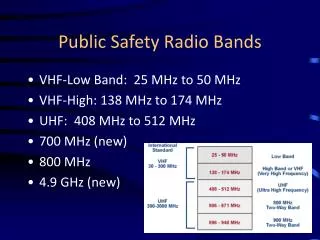
MultiRate DSP • In telecom systems that send and receive various types of signals (speech, video, text etc.), there is a requirement to process the various signals at different rates corresponding to the BW of the signal • Process of converting the rate of a signal to a different rate Sample rate Conversion • In analog domain (+arbitrary rates, - power, size) • Entirely in digital domain • Systems that employ multiple sampling rates in digital signal processing – Multirate DSP systems
MultiRate Signal Processing - Intro • Benefits • Improved flexibility for SDR multimode RX with same ADCs • RX • Typically digitization at sampling-rate significantly higher than BW - relaxing anti-aliasing filter specs • TX • Signals are created at minimum sampling-rate to avoid excessive computations – increased before DAC to relax interpolation filter specs
MultiRate Signal Processing - Intro • Cost • less MIPS less power, cost • Minimize the processed signal information to only concerned information • Base-station example • Digital extraction of diff. channels/users • Common RF and DAC • Drastic reduction of cost • Few RF comp. • Low-speed DSP comp.
MultiRate Signal Processing - Intro • Flexibility • simultaneous handling of multiple systems • IS-136 (30 kHz), GSM (200 kHz), IS-95 (1.25 MHz) and WCDMA (5 MHz) • ADCs fundamental trade-off between sampling rate and resolution • Multi-rate DSP allows designer more degree of freedom in system design • trade off sample-rate for resolution • Level of parallelism introduced • Level of introduced quantization error • System cost
Multirate DSP – SDR Context • In a software defined radio, one often has to deal with sampled wideband signals that contain a multitude of different user signals. • Part of the receiver's task is thus to extract the desired user signal(s) from such a wideband signal. • In such cases, the receiver may consist of multiple stages of down conversion and filtering. • After each down conversion and filtering stage, the output signal has a lower Nyquist frequency than the input. • Thus, it may be decimated before any further processing. As a result, one has to deal with signal processing scenarios where signals with multiple rates are to be dealt with.
Multirate DSP – SDR Context • The most basic blocks in multirate signal processing are M-fold decimator and L-fold expander. • Through interconnection of decimators/expanders and filters, we develop multirate signal processing structures that allow digital resampling of sampled signals to virtually any arbitrary rate. • Important are the rules governing the interconnection of signal processing blocks in multirate systems • Efficient structures for realization of multirate systems, known as polyphase filters • Multistage implementation • a powerful multirate technique for minimization of the complexity of multirate Systems. • Cascaded integrator-comb (CIC) filters, • a class of very low-complexity (multiplier-free) filters for interpolation and Decimation.
Sample-Rate Conversion Principles • Up-conversion vs. Down-conversion • Conversion of x(n) to y(m) n,m are indices for different time-scales • Sample rate converter can be thought of as a time-varying filter h(n,m) • Sampling Rate conversion factor –
Decimation • High-freq. information is eliminated from signal to reduce sampling freq. w/o aliasing • A sampled signal repeats it spectrum every 2π radians Need of a pre low-pass filter to avoid aliasing with cutoff (2π/D)*(1/2)
Decimation with Filtering • Low-pass filtering before performing decimation to avoid aliasing • The end-result of decimation is the content of the signal below π/D and with 1/D times lower sampling rate
Analysis of Decimation • Two processes involved • Low-pass filtering • Decimation
Interpolation • Interpolation = Up-sampling – increase the no. of samples of the desired signal • Used for matching sampling-rate requirements between two systems • As a last step before DAC to help relax requirements on reconstruction-filter • Several algorithms for re-construction • Zero-insertion • Zero-order-hold • Raised-Cosine Filtering • Fast Fourier Transform expansion
Zero-Insertion Interpolation • Two steps: • Insertion of zeros between signal samples • Low-pass filtering • No change in information, BUT spectral separation between images of original spectrum change • A contraction of the spectrum occurs a copy of the spectrum of the original signal is generated every 2π/I radians instead of every 2π • Direct mapping wy = ( wx / I ) 0 ≤ wx ≤ π maps to 0 ≤ wy ≤ (π/I)
Zero-Order Hold Interpolation • Space b/w two samples is filled with a sample generated using some function (ZOH function) • Computationally more expensive and generates less distortion at higher frequencies
Zero-Order Hold Interpolation • It has a low-pass filter version of zero-insertion form • The spurious signal content has been considerably reduced by the holding process compared to the zero-insertion interpolated signal for the same filter order • Attenuated images resulting from the process can be filtered out using an LPF with a cutoff frequency less than π/I • Introduction of some in-band distortion as well in the desired band.
Zero Order Hold Equivalent for a Sinusoid – Freq. domain Equiv.
Zero Insertion and Raised Cosine • Often along-with zero-insertion interpolation, raised cosine filter is used instead of low-pass interpolation filter • Up-sampling of PCM at TX • Up-sampling and raised cosine filtering is combined
Interpolation – FFT Expansion • Construct in Freq. domain the FFT of an up-sampled signal by using FFT of original signal • Procedure: • Separation between samples is Fs/N. • Zero-padding N(I-1) consecutive zeros between the positive and negative images • Performing an IFFT of the augmented signal • Resulting signal contains NI samples
Two Multirate Identities • Also called Noble identities • Multi-rate system = cascade of sample-rate alteration + digital filter • Sometimes changes in their position leads to computationally efficient realization keeping I/O relation unaltered • E.g. Placing the filter HD(zD), the impulse response of which is interpolated by D, in front of the downsampler is equivalent to downsampling a signal by D first and then passing it through an LPF HD(z) created by expanding the original filter impulse response by a factor of D