MAE 4261: AIR-BREATHING ENGINES
390 likes | 761 Vues
MAE 4261: AIR-BREATHING ENGINES. Air-Breathing Engine Performance Parameters and Future Trends Mechanical and Aerospace Engineering Department Florida Institute of Technology D. R. Kirk. LECTURE OUTLINE. Review

MAE 4261: AIR-BREATHING ENGINES
E N D
Presentation Transcript
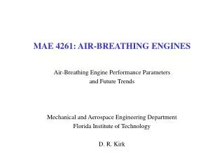
MAE 4261: AIR-BREATHING ENGINES Air-Breathing Engine Performance Parameters and Future Trends Mechanical and Aerospace Engineering Department Florida Institute of Technology D. R. Kirk
LECTURE OUTLINE • Review • General expression that relates the thrust of a propulsion system to the net changes in momentum, pressure forces, etc. • Efficiencies • Goal: Look at how efficiently the propulsion system converts one form of energy to another on its way to producing thrust • Overall Efficiency, hoverall • Thermal (Cycle) Efficiency, hthermal • Propulsive Efficiency, hpropulsive • Specific Impulse, Isp [s] • (Thrust) Specific Fuel Consumption, (T)SFC [lbm/hr lbf] or [kg/s N] • Implications of Propulsive Efficiency for Engine Design • Trends in Thermal and Propulsive Efficiency
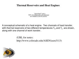
FLUID MECHANICS: DERIVATION OF THRUST EQUATION Chemical Energy Kinetic Energy Thermal Energy • Flow through engine is conventionally called THRUST • Composed of net change in momentum of inlet and exit air • Fluid that passes around engine is conventionally called DRAG
THERMODYANMICS: BRAYTON CYCLE MODEL • 1-2: Inlet, Compressor and/or Fan: Adiabatic compression with spinning blade rows • 2-3: Combustor: Constant pressure heat addition • 3-4: Turbine and Nozzle: Adiabatic expansion • Take work out of flow to drive compressor • Remaining work to accelerate fluid for jet propulsion • Thermal efficiency of Brayton Cycle, hth=1-T1/T2 • Function of temperature or pressure ratio across inlet and compressor
P-V DIAGRAM REPRESENTATION • Thermal efficiency of Brayton Cycle, hth=1-T1/T3 • Function of temperature or pressure ratio across inlet and compressor
EXAMPLE OF LAND-BASED POWER TURBINE: GENERAL ELECTRIC LM5000 • Modern land-based gas turbine used for electrical power production and mechanical drives • Length of 246 inches (6.2 m) and a weight of about 27,700 pounds (12,500 kg) • Maximum shaft power of 55.2 MW (74,000 hp) at 3,600 rpm with steam injection • This model shows a direct drive configuration where the LP turbine drives both the LP compressor and the output shaft. Other models can be made with a power turbine.
BYPASS RATIO: TURBOFAN ENGINES Bypass Air Core Air Bypass Ratio, B, a: Ratio of bypass air flow rate to core flow rate Example: Bypass ratio of 6:1 means that air volume flowing through fan and bypassing core engine is six times air volume flowing through core
TRENDS TO HIGHER BYPASS RATIO 1995: Boeing 777, FAA Certified 1958: Boeing 707, United States' first commercial jet airliner Similar to PWJT4A: T=17,000 lbf, a ~ 1 PW4000-112: T=100,000 lbf , a ~ 6
J85-GE-1 - 2,600 lbf (11.6 kN) thrust J85-GE-3 - 2,450 lbf (10.9 kN) thrust J85-GE-4 - 2,950 lbf (13.1 kN) thrust J85-GE-5 - 2,400 lbf (10.7 kN) thrust, 3,600 lbf (16 kN) afterburning thrust J85-GE-5A - 3,850 lbf (17.1 kN) afterburning thrust J85-GE-13 - 4,080 lbf (18.1 kN), 4,850 lbf (21.6 kN) thrust J85-GE-15 - 4,300 lbf (19 kN) thrust J85-GE-17A - 2,850 lbf (12.7 kN) thrust J85-GE-21 - 5,000 lbf (22 kN) thrust GE J85
P&W 229 Overview Type: Afterburning turbofan Length: 191 in (4,851 mm) Diameter: 46.5 in (1,181 mm) Dry weight: 3,740 lb (1,696 kg) Components Compressor: Axial compressor with 3 fan and 10 compressor stages Bypass ratio: 0.36:1 Turbine: 2 low-pressure and 2 high-pressure stages Maximum Thrust: 17,800 lbf (79.1 kN) military thrust 29,160 lbf (129.6 kN) with afterburner Overall pressure ratio: 32:1 Specific fuel consumption: Military thrust: 0.76 lb/(lbf·h) (77.5 kg/(kN·h)) Full afterburner: 1.94 lb/(lbf·h) (197.8 kg/(kN·h)) Thrust-to-weight ratio: 7.8:1 (76.0 N/kg) P&W F100 and 229
UNDUCTED FAN, a ~ 30 ANTONOW AN 70 PROPELLER DETAIL
EFFICIENCY SUMMARY • Overall Efficiency • What you get / What you pay for • Propulsive Power / Fuel Power • Propulsive Power = TUo • Fuel Power = (fuel mass flow rate) x (fuel energy per unit mass) • Thermal Efficiency • Rate of production of propulsive kinetic energy / fuel power • This is cycle efficiency • Propulsive Efficiency • Propulsive Power / Rate of production of propulsive kinetic energy, or • Power to airplane / Power in Jet
PROPULSIVE EFFICIENCY AND SPECIFIC THRUST AS A FUNCTION OF EXHAUST VELOCITY Conflict
COMMERCIAL AND MILITARY ENGINES(APPROX. SAME THRUST, APPROX. CORRECT RELATIVE SIZES) • Demand high T/W • Fly at high speed • Engine has small inlet area (low drag, low radar cross-section) • Engine has high specific thrust • Ue/Uo ↑ and hprop ↓ GE CFM56 for Boeing 737 T~30,000 lbf, a ~ 5 • Demand higher efficiency • Fly at lower speed (subsonic, M∞ ~ 0.85) • Engine has large inlet area • Engine has lower specific thrust • Ue/Uo → 1 and hprop ↑ P&W 119 for F- 22, T~35,000 lbf, a ~ 0.3
EXAMPLE: SPECIFIC IMPULSE SSME PW4000 Turbofan • Airbus A310-300, A300-600, Boeing 747-400, 767-200/300, MD-11 • T ~ 250,000 N • TSFC ~ 17 g/kN s ~ 1.7x10⁻⁵ kg/Ns • Fuel mass flow ~ 4.25 kg/s • Isp ~ 6,000 seconds • Space Shuttle Main Engine • T ~ 2,100,000 N (vacuum) • LH2 flow rate ~ 70 kg/s • LOX flow rate ~ 425 kg/s • Isp ~ 430 seconds
PROPULSIVE EFFICIENCY FOR DIFFERENT ENGINE TYPES [Rolls Royce]
OVERALL PROPULSION SYSTEM EFFICIENCY • Trends in thermal efficiency are driven by increasing compression ratios and corresponding increases in turbine inlet temperature • Trends in propulsive efficiency are due to generally higher bypass ratio
FUEL CONSUMPTION TREND • U.S. airlines, hammered by soaring oil prices, will spend a staggering $5 billion more on fuel in 2007 or even a greater sum, draining already thin cash reserves • Airlines are among the industries hardest hit by high oil prices • “Airline stocks fell at the open of trading Tuesday as a spike in crude-oil futures weighed on the sector” JT8D Fuel Burn PW4084 JT9D Future Turbofan PW4052 NOTE: No Numbers 1950 1960 1970 1980 1990 2000 2010 2020 Year
SUBSONIC ENGINE SFC TRENDS(35,000 ft. 0.8 Mach Number, Standard Day [Wisler])
AEROENGINE CORE POWER EVOLUTION: DEPENDENCE ON TURBINE ENTRY TEMPERATURE [Meece/Koff]
AIR-BREATHING PROPULSION SYSTEMSRAMJETSTURBOJETSTURBOFANS Daniel R. Kirk Assistant Professor Mechanical and Aerospace Engineering Department Florida Institute of Technology
RAMJETS • Thrust performance depends solely on total temperature rise across burner • Relies completely on “ram” compression of air (slowing down high speed flow) • Ramjet develops no static thrust Cycle analysis employing general form of mass, momentum and energy Energy (1st Law) balance across burner
TURBOJET SUMMARY Cycle analysis employing general form of mass, momentum and energy Turbine power = compressor power How do we tie in fuel flow, fuel energy? Energy (1st Law) balance across burner
TURBOJET TRENDS: IN-CLASS EXAMPLE(SEE INLET SLIDES FOR MORE DETAILS)
TURBOJET TRENDS: HOMEWORK #3, PART 1Tt4 = 1600 K, pc = 25, T0 = 220 K
TURBOJET TRENDS: HOMEWORK #3, PART 2a Tt4 = 1400 K, T0 = 220 K, M0 = 0.85 and 1.2
TURBOJET TRENDS: HOMEWORK #3, PART 2b Tt4 = 1400 K and 1800 K, T0 = 220 K, M0 = 0.85
TURBOFAN SUMMARY Two streams: Core and Fan Flow Turbine power = compressor + fan power Exhaust streams have same velocity: U6=U8 Maximum power, tc selected to maximize tf
TURBOFAN TRENDS: IN-CLASS EXAMPLE Improvement over turbojet: 4 – 2.4 → 66% at Mach 1 8 – 3.3 → 142% at Mach 0