Tiny Giants
Explore the basic hardware features, inputs/outputs, and programming options of the Alpha Controller. You can install it with ease and program it directly using the front panel or PC interface. The system supports multiple model sizes and power supply options for flexibility. Programming is intuitive with function-based blocks and graphic LCD display. The ALVLS software simplifies programming with visual icons and simulation capabilities.

Tiny Giants
E N D
Presentation Transcript
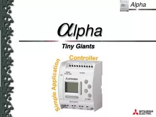
alpha Tiny Giants Controller Simple Application
Alpha Product Overview Programming Overview System sketch Ancillary Items Summary
Product Overview Basic hardware features Input / Outputs (I/O) devices Size / Installation RETURN
Basic hardware features Inputs Power supply Programming from the front of the Alpha (with 8 keys & LCD-display) Direct mounting Interface for PC-Programming Programmable operator interface (LCD-display) Interface for memory cassette Outputs
Basic hardware features • Options - model sizes: • Options - power supply model: • 24V DC • 100 to 240V AC (50/60Hz) • Options - expandability: • Network ‘slave’ cards ex. AS-I (20 I/O Alpha only) Inputs Outputs Model Inputs Outputs 6 I/O Alpha 4 2 10 I/O Alpha 6 4 20 I/O Alpha 12 8
Input / Outputs (I/O) devices • Options - Inputs: • Models with 24V DC power supply • 24V DC inputs (digital) • Up to 8 digital inputs can be re-designated through system software as being analogue inputs • Models with 100 to 240V AC power supply • 100 - 240V AC inputs (digital) • Options - Outputs: • Relay models - 8A per point at 240V AC / 24V DC • Transistor models - 1A per point at 24V DC
Model Width Height Depth 6 I/O Alpha 71.2mm 10 I/O Alpha 90 mm 55 mm 20 I/O Alpha 124.6 mm Size / Installation • Compact size: • (DC powered and AC powered units are the same size)
Size / Installation • Options - installation: • Directly on to DIN-rail • Directly on to the surface (by screws/bolts through integrally moulded location holes)
Size / Installation Direct mounting - using screws Direct mounting - using DIN-rail
Programming Overview Basic programming features Software Available instructions RETURN
Basic programming features • Function (block) based programming • Programming directly from the front of the Alpha • Graphic LCD-Display • 8 keys • Menu driven operation • System operation available in 5 languages(English, French, Spanish, German, Italian) • All information of one function block is displayed simultaneously • Option - Windows based software (95, 98, NT)
Programming directly from the front Monitoring Menu driven operation LCD-Display & 8 keys All function data displayed simultaneously
Programming basics • Programming is function (block) based • Each function is easily selected • Each function (block) carries out one task which has a number inputs conditions and resultant outputs • Up to 64 function scan be linked together (or up to 1500 bytes - which ever is exceeded first) • Each function (block) can be used as many times as required Analog values / special outputs / display outputs Digital input Digital inputs Digital output Analog input
Software - ALVLS • The software is called AL-PCS/WIN (ALVLS - Alpha Visual Logic System) • ALVLS works under 95, 98 and NT • ALVLS is a graphic based software which is available in 5 different system languages (English, French, Spanish, German, Italian) • Programming is possible with no previous experience • There is a system Wizard (to help create basic programs) • There are on line guides (to help use software functions) • Programming is based on selecting graphic icons which represent functions, placing them in a work area and connecting them up with a line. • There is an extensive help system (to provide general support)
Software - ALVLS • Icons can be personalised, I.e. users can add or customise their own • All programs can be simulated: • On-line simulation and monitoring requires the Alpha unit to be connected to the PC • Off-line simulation requires no Alpha unit as everything is self contained in the ALVLS software • ALVLS programs can be completely documented with comments for functions and added generic comments • ALVLS has a “system sketch” mode which allows users to create their own PC based operator interface
Software Input signals • Automatic identification of digital or analogue inputs depending upon the selected input image Internal Bits Input menu selection Buttons Inputs Scroll selection
Software Input signals • Analogue signals • Up to 8 inputs can be defined as analogue • Analogue input is 0 to 10V DC • Analogue resolution is 8 bits (0 to 255) • Analogue inputs are only available on 24V DC powered units Analogue signal is shown with a thicker connection line Example, AnalogInput Analogue or special signal is represented by green dot
Software Output signals • Graphical symbols and images make programs easier to understand Output menu selection Output types Scroll selection
Software graphical program simulation • Programs written with ALVLS software can be simulated to ensure correct operation. Input/Outputs status is toggled with line and function block status.
Instructions - Logic signals • Simple boolean commands OR(Or-Link) AND(And-Link) NOT (Negation) XOR (either/or) NOR (Or-Link negated ) NAND(And-Link negated)
Instructions - Logic signals • Complex boolean instructions can be created using the BOOLEAN function Easy to understand ‘sentence’ construction Word or symbol logical operators Simulation
Instructions - Status control • Self retaining command SET-RESET: • SET (set), RESET (set back) • Setting of priority • Status alternate (flip) ALT: • It function toggles the output whenever the input signal changes from OFF to ON. When clear input is ON, output becomes OFF irrespective of input status. • Time-function ONE-SHOT: • Time range 0.1 s–6553.5 s • This function is used to generate a single pulse with a specific duration
Instructions - Status control • Time function DELAY: • Time range 0.1 s–6553.5 s • Switch on-delay (on-delay) • Switch off-delay (off-delay) • Switch on- and off-delay timer,duration's can be set separately • Pulse generator function FLICKER: • Time range 0.1 s–6553.5 s • Pulse generator asymmetric(T-on, T-off individually adjustable) • Number of pulses adjustable or continuously • Total time of pulses adjustable or continuously • Time function PULSE: • Generates a pulse for one cycle when thefollowing are selected: • leading edge of one input • trailing edge of one input • leading and trailing edge of one input
Instructions - Event monitoring • Maintenance function HOUR-METER: • Next maintenance time is set - when reached an output is activated • Counting of working hours and minutes up to 32767 hrs and 59 min (1365 days, 3.7 years) • Counter value kept for 20 days after power is removed • Can be cascaded to increase time base • Counter function COUNTER: • Counting range up to 32767 • Output set when Count value reached • Count can be reset by input at any time • Counter function UP/DOWN-COUNTER: • Counting range: -32767–+32767 • Up/Down inputs are separate • Output set when Count value reached • Count set value can be manual setting, analogue input or fixed value triggered by digital input • Count can be reset by input at any time
Instructions - Event monitoring • Real time clock function CLOCK: • Data available from the real time clock: hours, minutes, day of the week, day of the month,month, year • 3 Formats to display the date: dd.mm.yyyy mm.dd.yyyy yyyy.mm.dd • Direct adjustment of the clock on the unit • Automatic adjustment of day and week • Automatic summer time/daylight saving time(US, UK, EU presets plus user configured option) • Max. 350 time events Example : Tuesday, 08.02.1999 10h30 08.02.1999 02.08.1999 1999.02.08
Instructions - Value processing • Analogue value processing GAIN: • Adjust Gain/Offset of read analogue values • Apply scaling to analogue input values • Compare-function with words COMPARE: • Comparison of 2 values (could be analogue, counter or timer values) • Types of comparison: =, <>, >, >=, <, <= • Schmitt-Trigger SCHMITT • Comparison of a value to 2 set pointstriggering different actions • Zone Compare (range on/off) ZON-CMP • Comparison of a value to a range(could be analogue, counter or timer values) • Types of comparison: =, <>, >, >=, <, <=
Instruction - User Interaction • HMI-Function DISPLAY: • LCD-Display on Alpha: 4 lines x 10 characters • The contents of display can be freely programmedwith text and/or values from programmed functions • Displayed values can be easily changed/edited usingthe keys on the front face of the unit
Instruction - User Interaction • To change a value through the HMI/Display option: • Press key: • First value is signaling • +1 at value, key • -1 at value, key • Confirming of change, key • Should the display consist of several values, selection of values with or with
System sketch RETURN
System sketch • ALVLS software, “Monitoring in System Sketch”: • In the ALVLS software it is possible to carry outmonitoring and/or simulation • Within the System sketch area, users can create avisual representation of their application(effectively creating a low function SCADA system) • Images can be imported (BMPs) and links to standard Windows programs can be made • User’s can copy any of the inputs/outputs or functionsused in the Alpha program to the System sketch area • By placing the devices in the System sketch and then activating either the simulation or the monitor mode’s - the users program can be controlled directly E.g………………..
Ancillary Items RETURN
Ancillary Items • The ALVLS software communicates to the Alpha unit through the computers serial port. This is connected to the Alpha unit with the AL-232CAB cable as shown below.
Ancillary Items • Memory cassettes: • By insertion of an EEPROM-cassette a new Alpha program can be directly inserted without aprogramming tool • Alpha has been designed to suit users needs: • Industry (IEC 1131.1, 2) • House- and building technique (EN 60730) • CE EMC • CE low voltage • UL/cUL.
Summary RETURN
SUMMARY Mitsubishi Electric, world leader in the sector of small PLCs launches something new on the market: The Alpha-Controller • Smaller and cheaper than a PLC, but with a lot of perfomance and new possibilities: • A totally innovative way of programming via the Alpha software • A big range of integrated functions • Display-Function • Outputs for up to 8 A • Real-time clock function • Standard analog inputs and corresponding functions. Alpha, Leader of the Function Controller Generation
Alpha Questions?
alpha Tiny Giants Controller Simple Application