Download
1 / 25
320 likes | 774 Vues
Non-Destructive Acoustic Metrology For Void Detection in TSV’s. Robin Mair Rudolph Technologies, Inc. 3D IC Drivers. Heterogeneous integration of RF, logic, memory, and sensors Performance-driven Interconnect speed and bandwidth, reduced power consumption Form-factor

E N D
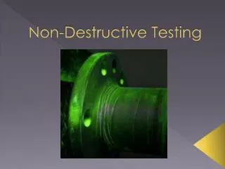
Non-Destructive Acoustic Metrology For Void Detection in TSV’s Robin Mair Rudolph Technologies, Inc.
3D IC Drivers • Heterogeneous integration of RF, logic, memory, and sensors • Performance-driven • Interconnect speed and bandwidth, reduced power consumption • Form-factor • Achieves highest capacity/volume ratio • Cost-driven • Cheaper than next gen lithography? Source: Yole, ITRS
TSV Scaling Roadmap “Via-middle”:Fabrication TSV’s after FEOL device fabrication processing but before BEOL interconnect Source: Eric Beyne, IMEC Technology Forum, Taiwan, September 2013. Source: IMEC
TSV Electroplating • Plating more challenging in TSV than damascene structures • Void formation dependent on plating chemistry • Void free fills require bottom-up fill, longer plating time and is expensive • Small voids migrate during processing to form larger “destructive” voids Aspect ratio typically ≥ 10:1
TSV Void Detection • FIB SEM • X-ray • Scanning Acoustic Microscopy • Laser-based Acoustics
Laser-Based Acoustics • Excitation laser of short pulse duration, launches acoustic waves in the sample. • Detection laser used to detect bulk waves or surface acoustic waves. Excitation Laser Detection Laser Surface waves Layer 3 Layer 2 Bulk waves Layer 1 substrate Simulation of measurement
Target Applications • Thick opaque films • RDL plating, MEMS, etc. - 10µm to 100’s of µm • Pillar / Bump • Diameter, thickness; Single and multi-layer Defects in bumps • Si:Si bonding • Delamination • Void Detection in Through Silicon Vias
Experimental Setup Generation laser: Short pulse (<~1nsec) duration generates a transient strain profile on sample which propagates as acoustic waves along surface and in bulk. Detection laser interferometer detects surface displacements when acoustic signal reaches detection location
Signal Generation and Detection in Cu vias probe pump 3 1. 4. 2. 3. Vertical Displacement (a.u.) Rapid heating of Cu by pump laser pulse – local thermal expansion Slowly decaying thermal response and propagating acoustic component Acoustic waves propagate down via and experience partial reflection at ‘interfaces’ (void, via bottom, …) “Echoes” returning to surface are detected with probe laser Delay Time (msec)
Signal Analysis 1 Subtract thermal background from raw signal Generate Periodogram • Apply Fourier Transform within a narrow time window. • Sweep time window through signal, repeating FT at each time step. • Generates 3-D map of FT amplitude vs Frequency and Delay Time
Signal Analysis 2 Feature 1 Feature 2 Apply image processing – Locate features Correlate feature shapes and locations to via and void dimensions Feature 1, Feature 2, … Via length, Void depth, Void size, …
Simulations – Sensitivity to Void Diameter FEM Simulation Skew • 10µm x 108µm via • Void at depth of 62µm • At 0.8µm, the void is discernible Void Dia =1.2mm Void Dia =1.6mm Void Dia =0.8mm Void Dia =4.0mm
Mapping Echo Features • FEM simulations performed for several via lengths • Processed in same way as real signals. • Periodograms (left) show the detected return echo. • Moves to later delay time as via length increases • Spreads (dispersion) as via length increases • Despite dispersion, centroids of echoes correlate very well with via length. Length = 40mm Length = 70mm Length = 100mm Length = 130mm
Propagation Speed Correlation: 10um vias: Depth(mm) = 1503.4*EchoTime(ms) – 12.5mm (propagation speed = 3060mm/ms) Correlation: 5um vias: Depth(mm) = 1509*EchoTime(ms) – 0.45mm (propagation speed = 3045mm/ms) • Guided mode propagation along the via probed. • Propagation speed is different from Cu sound velocity.
Sample A • Measured the same via as cross-sectioned • Find features in measurement which correlate to conical void and via bottom
Sample A (Cont’d) • Extracted feature times are used to assign depth • Results in good agreement with SEM
Sample B • Measured the same via as cross-sectioned • Find large voided region at bottom of via 1st Round Trip 2nd Round Trip
Sample B (Cont’d) 2nd Round Trip 1st Round Trip Findings: • See echoes representing bottom of Cu and the associated 2nd round trip. • Main echo is too early compared to expectation. • 2nd round trip echo is significantly more pronounced than expected for a properly filled via. • Observations 2 and 3 clearly point to a large bottom void.
Bottom Void Discrimination FEM Model • Relative amplitude of 2nd round trip (rt) echo (circled) is greater when the via has a void at the bottom • No Void: • 2nd round trip: ~13-18% (of 1st rt) • Bottom Void: • 2nd round trip: ~37-47% (of 1st rt) No void Bottom 10µm voided
Sample C & D • Measured vias were nearby on the wafer to the vias that were cross-sectioned. 5x50 Sample C Displacement (a.u) C D 5x50 Sample D Source: IMEC Delay Time (µs)
Sample C & D (Cont’d) Sample C Sample D (voided) Bottom of via Top of void
Sample C & D (Cont’d) • Extracted feature times for the dominant features at ~275MHz. • Correlate to thickness with relationship determined from simulations. • Results in good agreement with SEM Voided BKM
Summary • Laser based acoustics used to detect TSV voids • Small voids along length of via • Large bottom voids • Capability demonstrated for 10x100mm and 5x50mm • Capability for both as-deposited and post-CMP • Technique is • Non-contact, non-destructive • No coupling medium required • Continued development in data processing & new applications in packaging, MEMS, Storage
Acknowledgements We gratefully acknowledge the TSV samples and support provided by Michelle T. Schulberg, and James Chen of TEL NEXX and samples and FIB SEM data provided by Andy Miller and Leander Haensel of IMEC, Belgium. Thank You!