Download

1 / 20
200 likes | 341 Vues
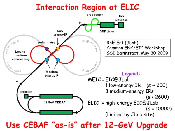
Overview and Issues of the MEIC Interaction Region. M. Sullivan MEIC Accelerator Design Review September 15-16, 2010. MEIC IR and detector Backgrounds SR Radiative Bhabhas Summary Conclusion. Outline. The MEIC Interaction Region Features 50 mrad crossing angle

E N D
Overview and Issues of the MEIC Interaction Region M. Sullivan MEIC Accelerator Design Review September 15-16, 2010
MEIC IR and detector Backgrounds SR Radiative Bhabhas Summary Conclusion Outline
The MEIC Interaction Region Features 50 mrad crossing angle Detector is aligned along the electron beam line Electron FF magnets start/stop 3.5 m from the IP Proton/ion FF magnets start/stop 7 m from the IP MEIC Interaction Region Design
Electron beam Energy range 3-11 GeV Beam-stay-clear 12 beam sigmas Emittance (x/y) (5 GeV) (5.5/1.1) nm-rad Betas x* = 10 cm x max = 435 m y* = 2 cm y max = 640 m Final focus magnets Name Z of face L (m) k G (11 GeV) QFF1 3.5 0.5 -1.7106 -62.765 QFF2 4.2 0.5 1.7930 65.789 QFFL 6.7 0.5 -0.6981 -25.615 Table of Parameters (electrons)
Proton/ion beam Energy range 20-60 GeV Beam-stay-clear 12 beam sigmas Emittance (x/y) (60 GeV) (5.5/1.1) nm-rad Betas x* = 10 cm x max = 2195 m y* = 2 cm y max = 2580 m Final focus magnets Name Z of face L (m) k G (60 GeV) QFF1 7.0 1.0 -0.3576 -71.570 QFF2 9.0 1.0 0.3192 63.884 QFFL 11.0 1.0 -0.2000 -40.028 Table of Parameters (proton/ion)
The magnet apertures are usually set by the required BSC Making the BSC generous forces larger aperture final focus magnets – usually these are more difficult magnets to build However, a large BSC improves machine flexibility by allowing for smaller beta* values (and hence larger beta max values) if the accelerator can operate with fewer beam sigmas than that defined by the BSC and backgrounds are acceptable The MEIC 12 sigma BSC definition is a reasonable compromise Magnet apertures
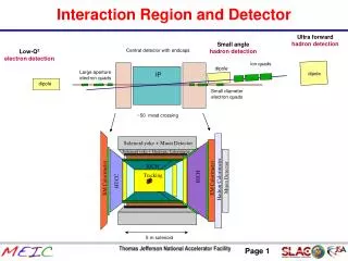
Ultra forward hadron detection Small angle hadron detection Central detector with endcaps Low-Q2 electron detection ion quads dipole Large aperture electron quads IP dipole dipole Small diameter electron quads ~50 mrad crossing Solenoid yoke + Muon Detector Solenoid yoke + Hadronic Calorimeter RICH Tracking RICH Muon Detector EM Calorimeter EM Calorimeter Hadron Calorimeter HTCC Interaction Region and Detector Courtesy Pawel Nadel-Tournski and Alex Bogacz 5 m solenoid
4 3 Tesla 2 1 QFFP QFFP QFFL QFF2 QFF1 QFF1 QFF2 QFFL ~2 kG Estimate of the detector magnetic field (Bz) The detector magnetic field will have a significant impact on the beams. Some of the final focusing elements will have to work in this field.
Both beam energies have a fairly large energy range requirement The final focus elements must be able to accommodate these energy ranges An attractive alternative for some of the final focusing elements (especially the electron elements) is to use permanent magnets – they have a very small size and do not need power leads However, any PM design has to be able to span the energy range (for instance, only 30% of the final focus strength can be PM) Energy range
First look at SR backgrounds 50 mrad Synchrotron radiation photons incident on various surfaces from the last 4 electron quads 38 P+ 8.5x10⁵ 2.5W 4.6x10⁴ 240 2 e- 3080 Rate per bunch incident on the surface > 10 keV Beam current = 2.32 A 2.9x10¹⁰ particles/bunch X Rate per bunch incident on the detector beam pipe assuming 1% reflection coefficient and solid angle acceptance of 4.4 % Z Electron energy = 11 GeV x/y = 1.0/0.2 nm-rad M. Sullivan July 20, 2010 F$JLAB_E_3_5M_1A
5 times larger beam emittances and lower beam energy 50 mrad Synchrotron radiation photons incident on various surfaces from the last 4 electron quads 7 P+ 1.6x10⁵ 0.5W 9.0x10⁴ 1.8x10⁵ 4 e- 6.4x10⁵ Rate per bunch incident on the surface > 10 keV Beam current = 2.32 A 2.9x10¹⁰ particles/bunch X Rate per bunch incident on the detector beam pipe assuming 1% reflection coefficient and solid angle acceptance of 4.4 % Z Electron energy = 5 GeV x/y = 5.5/1.1 nm-rad M. Sullivan July 20, 2010 F$JLAB_E_3_5M_1A
Beam tails Assumed beam tail distribution is the same as was used in PEP-II background calculations The tail distribution is primarily driven by the beam lifetime The SR background is dominated by the beam tail particles
Initial look at synchrotron radiation indicates that this background should not be a problem but a more thorough study is needed Need to look at lost particle backgrounds for both beams Proton beam has been studied extensively Generally one can restrict the study to the region upstream of the IP before the last bend magnet A high quality vacuum in this region is sometimes enough Backgrounds
There is a luminosity background from the electron beam During the collision the electron can radiate a photon This was a major source of neutrons in the B-Factory detectors Radiative Bhabha Background
B-Factory Radiative bhabhas Off energy beam particles were swept out of the beam and then hit the local vacuum pipe
B-Factory Radiative Bhabhas Both B-factories experienced this luminosity background
The super B-factories (SuperB and superKEKB) have designed the IR so that this background source is minimized This background has become one of the primary design drivers for the interaction region The other background that is close to being a design driver is the two-photon process where the produced background comes from low-energy e+/e- pairs produced from the interaction This background should not be a factor in the MEIC design (down by another factor of ) Super B-factories
The radiative bhabha background may not be as important for the MEIC as it was for the B-factories but there will be beam induced backgrounds in the low angle detectors for the low-Q2 detectors and this reaction will be very similar to the physics signal looked for here Ultra forward hadron detection Small angle hadron detection Central detector with endcaps Low-Q2 electron detection ion quads dipole Large aperture electron quads IP dipole dipole Small diameter electron quads ~50 mrad crossing MEIC
The IR is one of the more challenging regions to design There are multiple constraints, however, balancing the various requirements to maximize the physics is always the primary goal of any design The beam induced backgrounds many times control a large part of the design of the interaction region in order to allow the detector to operate in what can be a very hostile environment Summary
A careful study of the beam induced backgrounds is always an important aspect of any interaction region design As the accelerator design evolves one must constantly recheck backgrounds to make sure the changes do not have an adverse effect on rates There is always room for unexpected backgrounds so diligence in controlling and understanding backgrounds always tends to pay off Conclusion