Download
1 / 43
430 likes | 536 Vues
This document outlines the intricate support system designed for the interaction region of BEPCII at the IHEP. It details the movable stage, including its components such as the driving base and detachable stage, capable of precise movement and alignment of superconducting (SC) magnets. Emphasis is placed on the support structure's ability to accommodate SC magnets (SCQ, ISPB, Q1a, Q1b) while ensuring stability against magnetic forces. The document also discusses methods for stress intensity computation and natural frequency analysis, contributing to the system's robust engineering design.

E N D
Support system in the Interaction Region of BEPCII Wang Mo Tuo Accelerator Center of IHEP 2004.1.8
Support system in the Interaction Region • Description of the support system • The movable stage • The driving base • The detachable stage • How to support the SC magnet • How to align the SC magnet with supports • Computation of the stress intensity of support • The natural frequency analyses on support • The mode analyses on support system with SCQ, ISPB, Q1a, Q1b magnets
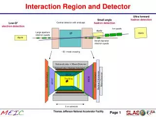
Description of the Support system • In interaction region the magnets that will be symmetrically placed are SCQ , ISBP, Q1a, Q1b, and IQ2/ OQ2.
Description of the Support system To dig rectangle pit
Description of the Support system The support system included the movable stage, the driving base and detachable stage. The movable stage can move along the beam axis 2.8 m approximately.
The movable stage The movable stage not only supports the SCmagnet but also serves as a common support base for the ISPB, Q1a, Q1b magnets and other vacuum equipments. The SC cryostat, LHe transfer line and valve service cryostat are supported by the movable stage too.
The movable stage The SC cryostat and ISPB magnets can be pulled out and pushed into the BESIII. The Q1a, Q1b will be moved with them together. The diameter size of place to locate SC cryostat in BESIII is Ø800mm. The end-can diameter is Ø635mm, in this way the outer diameter of the cantilever section is about Ø 700mm. Themovable stage consists of three parts. They are upper part , middle part and bottom part .
The movable stage • The upper part that support the SC cryostat and ISBP, Q1a and Q1b magnets can be accurately adjusted in three degree of freedom . (moving along vertical axis ‘∆Y’, rotating around transverse axis ‘θX’ and longitudinal axis ‘θZ’ ) It is made of non magnetic stainless steel 304. It is a kind of cantilever of welding structure.
The movable stage • The middle part can be accurately adjusted along the rest directions. The positioning of the SC magnets are carried out by adjusting the upper part and middle part. Other three magnets are adjusted by the simple mechanism of their own. It is made of general steel Q235A. It is a welding frame with baseplate. There are 6 support points, 8 press bolts and 8 adjusting lock nuts.
The movable stage • The bottom part is fixed on the driving base. On the bottom part there are 8 connecting bolts and adjusting screws, which hold the middle part.
The driving base • The driving base likes a machine tool body. Two rolling guides and one ball screw are installed on it. The moving speed of movable stage can be controlled by step motor. The terminal switches are installed at both ends. This driving base is about 4 m long.
The detachable stage • There is a detachable stage on the driving base. The IQ2 and OQ2 magnets are located on the detachable stage. The positions of these magnets are adjusted by their own mechanism. The detachable stage can be dismounted and remounted accurately, when the movable stage is pulled out or pushed into the BESIII.
How to support the SC magnet All the coils of SC magnets in each side of the IP are contained in a single SC cryostat vessel. The support plate is contacted at the front end of the SC cryostat end-can by connecting bolts. coils Supportconnect
How to support the SC magnet The SC cryostat serves as containing vessel for holding the SC coils and also serve as the support structure to connect with the support stage which located outside BESIII detector. The SC cryostat has to be installed inside the BESIII detector. The both of SC cryostat and support are designed to withstand the forces that caused by the magnetic field of the coils and their interactions with the BESIII solenoid field.
How to support the SC magnet • The movable stage is connected with the SC cryostat at the front plate of the SC cryostat end- can by 17 connecting bolts and 2 pins. (It is illustrated with next drawing) Next the end-can are L-He transfer line and the service cryostat. The outer diameter of the end can is 635 mm with 30mm vertical shift for the L-He transfer line connected port.
A cross section view of connection between SC magnet and support’s front board
How to align the SC magnet To achieve the positions of each of left and right SC magnets with the upper parts together, they will be fixed by the 8 pair of adjusting bolts on the upper part and the bottom part . There are two glass hole in BESIII, so allow the surveyors to look through the pair of optical alignment tube in the left and right . In this way, the pair of the SC magnets can be aligned within 0.15 mm. The positions of SC cryostat, ISBP, Q1A and Q1B magnets will meet the physical requirements by adjusting mechanism.
How to align the SC magnet As regards the SC magnet displacements caused by the magnetic force, they can be measured by four couples of probes installed on the surface of SC cryostat and inner surface of BESIII MDC relatively. The closed orbit distortion due to the misalignment of those magnets can be minimized by means of controlling magnets current. The setting process which in neighborhood of the crowded beam line near the IP needs for studying.
Computation the stress intensity of support system The SC cryostat allowable displacements caused by the magnetic force must be controlled under about 0.6mm. In order to decrease the displacements of SC cryostat, the designed structure of support system must be enough rigid and stable. So we computed the stress intensityandthe displacement of support structure model.
Computation the stress intensity of support system The first step taken was the simulation computation using conventional formulation for the cantilever section model. The result is about 0.3mm. (at the front end of SC cryostat) Second, we computed the displacement of the movable stage upper and middle parts with the ANSYS code. The results are: 0.196 mm(Didn’t load the 10.5KN force to out of BESIII) and -0.139 mm(load all force). The maximal stress is 82.1MPa, which is less than the permissible stress (235MPa) of general steel Q235A, at the supporting bolts between the upper part and the middle part.
Computation the stress intensity of support system The three-dimension model of movable stage for Finite Element Analysis
Computation the stress intensity of support system The Meshed 3D model of support system by <ANSYS> code
Computation the stress intensity of support system The displacements of the SC cryostat is -0.139 mm (Didn’t load the 10.5KN force to out of BESIII)
Computation the stress intensity of support system The displacements of the SC cryostat is 0.196 mm ( for all loads)
Computation the stress intensity of support system The displacements of the SC cryostat is 1.25 mm including weights of support and SC magnets.
Computation the stress intensity of support system The maximal stress is 82.1MPa (at the supporting bolts)
The natural frequency analyses on support • We computed the natural (inherent) frequency of the supports system by the ANSYS code too. They are: 17.13 Hz, 32.79 Hz, 70.08 Hz, 96.34 Hz, 110.62 Hz, 145.51 Hz…. (The computation has not included mass of the ISPB and Q1A, Q1B magnets. )
The natural frequency analyses on support The lowest first order natural frequency
The natural frequency analyses on support The second order natural frequency
The natural frequency analyses on support The fourth order natural frequency
The mode analyses on support system with SCQ, ISPB, Q1a, Q1b on We computed the natural (inherent) frequency of the support system by ANSYS code again. This time has included masses of the ISPB and Q1A, Q1B magnets. They are: 19.808 Hz, 29.999 Hz, 49.907 Hz, 68.816 Hz, 71.642 Hz, 81.966 Hz….
The mode analyses on support system with SCQ, ISPB, Q1a, Q1b on
Analysis model of SC magnet, ISPB, Q1a, Q1b magnets and Support
Support system in the Interaction Region Thanks all experts and everyone!