Interaction Region Transport System: Optics and Issues
170 likes | 311 Vues
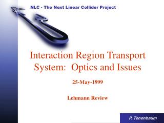
Interaction Region Transport System: Optics and Issues. 25-May-1999 Lehmann Review. P. Tenenbaum. Interaction Region Transport Schematic: Betatron Functions. Operating range (CM energies) Energy Bandwidth SR in bends, quads power deposition emittance dilution

Interaction Region Transport System: Optics and Issues
E N D
Presentation Transcript
Interaction Region Transport System: Optics and Issues 25-May-1999 Lehmann Review P.Tenenbaum
Operating range (CM energies) Energy Bandwidth SR in bends, quads power deposition emittance dilution Backgrounds and Beam Stayclears IR Layout and Technology Crab Cavity Tight Tolerances Position jitter and drift Magnet Field jitter and drift Magnet Roll Magnet Harmonics Machine Protection Extraction of Disrupted Beam Diagnostics and Operations IRT Issues
Center-of-Mass Operating Range • All magnets OK from 350 GeV to 1 TeV CM except last quad • Last quad: needs to be changed at ~750 GeV CM • Tunnel length set for 1.5 TeV CM • Above 1 TeV CM: Weaker CCX/CCY bends, move magnets 13 cm (x), new doublet, new sextupoles
Energy Bandwidth • Limited by higher-order chromatic effects • Some improvement possible with sextupoles at IP images (“Brinkmann” sextupoles) • Limited at low energy by larger emittances (chromogeometrics) • Another optimization pass needed
Synchrotron Radiation • SR in CCX/CCY bends breaks chromatic correction • SR in FD limits spot size (“Oide Effect”) • Conflict: • Bandwidth likes strong bends, short quads • SR likes weak bends, long quads • SR power in 10 mrad arc: 6.3 kW (1 TeV CM), 22 kW (1.5 TeV CM)
Backgrounds and Beam Stayclears • Collimate at ~ 5 sx, ~ 35 sy, 4% energy (collimation), 7 sx, 42 sy (CCX/CCY) • Stay-clears: 14 sx, 60 sy or better: vacuum system has 1.2 cm OD (IP Switch Beta Match), 3.0 cm OD (CCX FD), 2 cm 1.28 cm OD (FD) • Soft bend (11 gauss @ 1 TeV CM) separates bend SR from detector • Still an area which needs considerable study!
IR Layout and Technology • Need to focus beam down to nanometer sizes • Accommodate extraction line for disrupted beam • Cope with collision debris • Final Doublet has exciting mix of technologies (PM, SC, Fe), mechanical conflicts • Support of doublet (in detector) a problem (optical anchor?) • Magnetic distortions of solenoid (6 T) solved problem
Crab Cavity • Large Crossing Angle + Small Beams = Crab Cavity needed • Crab cavity relative phase tol = 0.2° (X-Band) or 0.05° (S-Band) • X-Band cavity has lower power, fewer cells • S-Band cavity has larger aperture
Tolerances • Position jitter and bend field jitter • deflect beams at IP -- they do not collide • Quad field errors • shift waist at IP • Sextupole position errors • introduce waist, dispersion, coupling errors at IP • Quad position drift • deflects beam between sextupoles, or • introduces dispersion • Quad rolls produce xy coupling (unflattens beam) • High-order multipole content dilutes emittance • Made much worse in CCX/CCY/FTrans (large b’s)
Typical Tolerances By Region(Most challenging tolerances highlighted) Above tolerances are for 2% Spot Size growth / aberration Still need to develop more detailed tolerance budget...
Machine Protection • Similar to linac system: only slow steering devices permitted, orbit and magnet strengths monitored • Generally less severe than in linac • no irises, so beam hits at glancing angle • beam is very large in many spots • Commissioning requires: • pilot beams • high-powered pulsed dump (end of linac) • low-powered pulsed dump (entrance to beta match) • very-low-powered insertable stopper (entrance to doublet) • Not yet a solved problem
Extraction of Disrupted Beam • Post-collision beam has large emittance and energy spread • 1 MW of power beamstrahlung photons • Ideal solution: 1 high-power dump for photons and electrons • Need to minimize losses in dumpline (backgrounds) • Possible backgrounds from dump backshine • Need to measure polarization, energy spectrum of post-collision beam • For NLC beam, 0.25% of power = whole SLC beam!
Diagnostics and Operations • 1 BPM/quad, 1 mm resolution; several RF cavity BPMs, resolution ~ 30 nm • 10 wire scanners for incoming e, beta matching, extracted beam measurements • 5 skew quads, 4 small sexts for static aberration tuning • All quads and All sexts on movers, No power supply stringing for quads/sexts • Many feedbacks which can in principle ease our tolerances • More study of this area is needed...
Re-optimize bandwidth of FF Detailed background studies/ collimation (inc. vacuum) Complete IR design, eliminate conflicts, IP anchor Crab cavity design/feedback Better, more optimal tolerance budget, specs for optical correction magnets Complete study of MPS issues: are sacrificial collimators needed? Additional work on extraction line: 2 high-power dumps? Handle lost beam power Instrumentation Much more detailed study of feedback and tuning “cradle to grave” simulation of tuning strategy Quantitative understanding of feedbacks study full linac-to-IP transport with feedbacks Work Still to be Done