Download

1 / 4
40 likes | 135 Vues
UnFramed Canopy Fitting Instructions V3.0. Contents – 1 x handle pack 12 x 30mm Wood Screws 4 x M8 flat washers 3 keys 1x door 4 x M8 - 50mm coach screws.

E N D
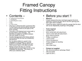
UnFramed Canopy Fitting Instructions V3.0 Contents – 1 x handle pack 12 x 30mm Wood Screws 4 x M8 flat washers 3 keys 1x door 4 x M8 - 50mm coach screws. This door is delivered with a protective film To the Frame only and should be removed now if fixing the frame to the back of the brick opening . This door is CE Marked and comes with a Europe wide 2 year warranty , the warranty is subject to conditions please see your dealer or visit www.Fort doors.co.uk for terms . Caution Garage doors Are heavy and we recommend that this item be installed by two persons Do not allow children to assist in the installation of this product or use the product un-assisted , garage doors can inflict severe injury if not used correctly . Always ensure the door is correctly adjusted and serviced failure to do so may invalidate the warranty . This does not effect your statutory rights . Wear eye protection and gloves as garage doors have sharp edges . Before you start !! Measure Check measure the door and frame against the brick opening to ensure the door will fit into the opening and then open when installed , also check the frame is square . Check the space required inside the garage that the door will not be impeded by anything in the garage . Frame Requirement This door is ready to install to your timber frame , this must be a minimum 60mm square (ideal size 70mm square ). It must also be sound and free from any rot , splits or damage , garage doors are under extreme pressure from the spring system and a poor frame condition could lead to serious injury if the frame breaks or fails in any way . Tools required Cordless Drill. (or powered) Phillips screwdriver . 10mm socket 10mm ring spanner . Timber wedges for levelling Spirit level Set of Alen keys (if adjustment to spring required) Fixings not supplied Light Oil (3in1) Slamming strip 1’’ x 1’’ timber
Installation Until all parts of the installation are finished there’s a possibility of being locked out , always ensure someone is inside until you have checked the operation of the locking and adjusted as required. Remove the side tracks by cutting the cable ties note the correct arrangement of the bottom wheel as this is vital later . (Fig1)Note the square holes are at the upper part of the track not the bottom . Measure the door panel and the precise location of the top latch assembly , now fit two spring holders as shown (Fig 2) using 3 x 30mm wood screws . (alternatively place door in opening and mark where latches are to be fitted ). Offer the door up to the opening (two persons required ) and wedge in to place ,hook the spring over the spring holders and wedge the door in position , remove the spring transit bracket (fig 3) use a spirit level to ensure the overall satisfactory look of the installation and in particular the level of the frame head is correct . Now check the following – the red and white drum do not foul the brickwork either side . The cables run from the back of the cones against the frame to the wheel assembly . When satisfied with the door position move the spring left or right so that the side arms are level either side (ensure the black side seal on the door can pass through the arms (Fig 3) the bracket on the left is not fixed and you should ensure this is pushed tight against the white drum Now using the 2 x 50mm coach screws fix the top spring assembly into place the bottom edge of the bracket should be in line with the bottom edge of the frame head . Slide the left and right side track over the wheel and anti drop device as shown in fig 1 the bottom edge of the track should be around 35mm below the bottom edge of the wheel , fix the track in place ! Caution if this is not level the door will be difficult to operate , this can be adjusted later if required . Fig 2 Fig 1 Fig 3
Now pull the pin that is used to secure the tension during transport , this can be quite stiff as it holds the spring pressure , work it side to side to ease it free. Now slowly open the door and check that the side runners are positioned correctly at the top as shown in fig 1 . If not positioned correctly the door will not be smooth in operation . Now fit the handle as shown. Fit the outer handle to the outside of the door , fit the inner lock and the moulded fixing using an Alan key and tighten (Caution !! only tighten enough to remove play from handle , over tightening can damage the outer panel ) Open the door fully and oil the side runners and the wheels / cables and top latches . If 4 point locking purchased see separate sheet and fit now . Caution !!Check the locking works correctly from the inside by closing the door and opening again , do not do this from the outside as if adjustment is required you may not be able to open the door again .Although adjusted in the factory the cables can be disturbed during transport and it is the responsibility of the installer to correct the cables as required . Now oil the tracks / lock and latches and all moving parts – do not grease any part . Adjustment – if the door is opening too slowly or too quickly increase the tension on the spring .Call 0121 749 7977 for advice .This element should only be performed by competent persons . Finish the door frame with trim as required . Locking cables and lifting cables are subject to wear and tear and should be examined regularly , tangling of cables through poor maintenance / adjustment does not constitute as a manufacturing defect. Technical helpline 01217497977 Email sales@fortdoors.co.uk www.fortdoors.co.uk
Removal . To remove the door you first must replace the spring tension holder shown on page 3 . Remove side track screws and slide out the tracks , undo the spring holder bracket screws x 4 and lift the entire spring spring assembly off the locking point/ spring holder and lower the spring to the mid point of the door . Ease the door out of the opening . Every 3 months you must oil all pivot points with 3 in 1 oil , you must check tension of the door ( open the door and ensure it holds in place if it falls contact your dealer or the helpline for more advice ) Clean the paint finish and touch up any marks with the correct Ral colour stick available from your dealer . Refer to the door label for more advice .