Download
1 / 26
270 likes | 446 Vues
LHCb VELO Upgrade Strip Chip Option: Data Processing Algorithms. * AGH-Krakow. Giulio Forcolin , Abdul Afandi , Chris Parkes, Tomasz Szumlak *. Part I: LCMS and/or MCMS? Part II: Effect of 6-bit ADC Part III: Zero suppression Part IV: Data Output Rate. Current VELO Data Processing.

E N D
LHCb VELO Upgrade Strip Chip Option: Data Processing Algorithms * AGH-Krakow GiulioForcolin, Abdul Afandi, Chris Parkes, Tomasz Szumlak* • Part I: LCMS and/or MCMS? • Part II: Effect of 6-bit ADC • Part III: Zero suppression • Part IV: Data Output Rate
Current VELO Data Processing • Data digitized and processed on TELL1 board • 10 bit ADC • Processing algorithms currently used • Pedestal Subtraction • Common Mode Suppression (in units of 32 chan.) • Strip Reordering • Zero-suppression and Clusterisation
Planned Changes for Study • Algorithms currently implemented on the TELL1 board for VELO will move to the SALT chip • Reduce the ADC count from 10 bits to 6 bits • Use a Common Mode Suppression (CMS) algorithm that uses all 128 channels in a chip • Options are: • MCMS, Mean Common Mode Suppression, find the average of a set of channels, and then subtracts this from the individual readings • LCMS, Linear Common Mode Suppression, fit a line to a set of 128 readings and then subtract this line from the data • To simplify the electronics, perform only Zero Suppression and no Clustering
Method • Used algorithms based on the Vetra algorithms • Performed algorithms in the order Pedestal Subtraction, MCMS, LCMS and Zero Suppression • Used integers to simulate the limited number of bits available on the electronics; this was achieved by truncating all the numbers after the units. • (i.e. equivalent to bit shifting rather than rounding) Data Samples No beam data from 2012 (Run 113600) Beam collision data from mid/late 2011 (Run 98228, μav= 1.39)
Part I: LCMS and/or MCMS? • Studies with 10-bit ADC • Using data taken with no beam
Raw Data • For the first step, data with no hits was studied
Pedestal Subtraction • Pedestals calculated as the average of the readings of each channel • Then subtracted from the data • Due to integerization, the distribution was not centred around 0 • Fix by adding 0.5 to the average pedestal value, and 0.5 t during calculation,
Noise after MCMS and LCMS • MCMS has a significant effect, simple algorithm • LCMS is not a great improvement, (5% improvement in noise) • It is a lot more processor intensive than MCMS • Conclude – current data suggests only need to perform MCMS, and future proof should CM increase • (caveat: new VELO will move closer to beam, but no sign of significant beam pickup )
Part II: Effect of 6-bit ADC • Rescaling from 10-bit ADC to 6-bit ADC • But making better use of dynamic range • Using no beam data
Data Scaling • Data was scaled to make it compatible with limiting ADC counts to 6 bits • The aim was to allow a signal of two minimum ionising particle (equivalent to ~80 ADC counts above the noise in the current data) • [Achieved by subtracting 480 counts from the raw data, and dividing what was left by 3] • Algorithms were then carried out as before (with truncation to 6 bits)
Results with 6-bit ADC Use of 6-bit ADC increases effective noise by 35% Can counteract to measure noise by rescaling ADC 10 bit processing noise = 2.38 [10 bit ADC] 6 bit processing noise = 1.13 [6 bit ADC] = 3.39 [10 bit ADC] 10 bit processing noise = 1.99 [10 bit ADC] 6 bit processing noise = 0.88 [6 bit ADC] =2.64 [10 bit ADC]
Results with other rescaling [Achieved by subtracting 480 counts from the raw data, and dividing what was left by 2] 10 bit processing noise = 2.38 [10 bit ADC] 6 bit processing noise = 1.63 [6 bit ADC] = 3.26 [10 bit ADC] 10 bit processing noise = 1.99 [10 bit ADC] 6 bit processing noise = 1.14 [6 bit ADC] =2.28 [10 bit ADC] • Rescaling the data by a factor of 2 increases effective noise by 15%, however it would not be possible read a 2 MIP signal using this scaling, would need 7-bit ADC. • Using 8-bit ADC would remove the need for scaling and still save 2 bits
Part III: Zero suppression • Using one simple threshold to zero-suppress • Using late 2011 data (after radiation damage)
Zero Suppression (ZS) • To simplify the design of the electronics it has been decided that they (if possible) should only perform Zero Suppression • Clustering would then be performed on TELL40 • This means that no reordering needs to be performed at this stage • i.e. even were it needed it could be done on the FPGA • Zero Suppression performed by only reading out signals above a certain threshold • E.g. look for reading 4σ above the noise level
Zero Suppression (ZS) • Setting threshold of 4σ excludes almost all of the data for the no-beam data set • Integerization causes there to be a difference in the number of readings between the two sets of data
Zero Suppression (ZS) • Threshold set at 10 [10-bit ADC counts] or 3 [6-bit ADC counts] • It appears a lot of “noise” is outputted even if the threshold is 4σ above noise level • This “noise” is not present in no beam data, probably due to radiation damage second metal effect • In 6-bit ADC integerization is significant (10 in 10-bit would be 3.3 in 6-bit) and can lead to significant increase in noise 10-bit ADC 6-bit ADC
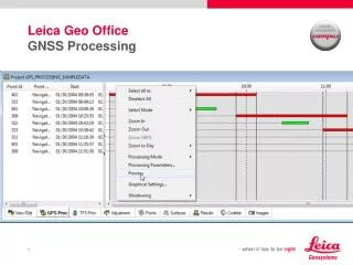
VELO R Sensor Chris Parkes
VELO R Sensor 2nd Metal Layers Chris Parkes
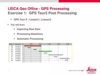
Jon Harrison Cluster Finding Efficiency 2nd Metal Layer Charge Loss Chris Parkes
Part IV: Data Output Rate • Studies of data size given different protocols for data output
Data output rate • Have 27-28 bits that are sent out once for each event • Channel ID and ADC count sent out for each channel with a reading above the threshold • Number of channels that can output data limited by payload size (above this saturate)
Data output Rate 3 Options to output data • Output Bunch ID, Sensor ID and Chip ID for each bunch crossing while the Payload Size, is sent out only when at least 1 hit is present • Output Bunch ID, Sensor ID, Chip ID and Payload Size for each bunch crossing • Output Bunch ID, Sensor ID, Chip ID and Payload Size only when at least 1 hit is present For each of these options can have a payload size of either 3 or 4 bits; therefore the number of readings that can be outputted is limited to • 8 or 16 • 7 or 15 • 8 or 16
Data output Rate • Assume a bunch crossing every 25 ns • Assume that there is a certain occupancy rate, P, for each channel to register a hit • For a probability of P = 1%, expect 5.12x10⁷ readings per chip per second • For a probability of P = 2%, expect 1.02x10⁸ readings per chip per second • Use a Poisson distribution to calculate the probability that each chip records a certain number of hits • Can therefore calculate the expected data output rate for each chip
Data Output Rate For a single chip
Observations • If payload size is limited to 3 bits, expect to lose up to 0.26% of readings if the P ≤ 2%, however the data rate is also reduced by ~1.5% compared with 4 bits • For P = 1%, the data rate is reduced by ~15% when sending headers only when data is present (option 3), however for P = 2%, it is only reduced by ~3% • Option 2 increases data rate by ~2%, however should be easier to implement. • Conclude: • 1) Need detailed knowledge of occupancy rate to make decision on whether send headers out is significant • 2) 3-bit for payload size seems sufficient for 2% occupancy
Conclusions • MCMS needed, but not LCMS • 6-bit ADC, integerization causes 25% increase in measured noise • Zero-suppression in 6-bits • Needs further study. 2nd metal layer effect could cause a problem if at upgrade. • Data rates: 3 bit payload size, rate at 2% occupancy ~ 0.27Gbytes s-1 per chip