Download
1 / 28
280 likes | 422 Vues
GASTOF Cherenkov with RF Phototube for FP420. Amur Margaryan. Timing Workshop Krakow 2010. 1. Contents. Introduction RF time measuring technique Radio Frequency Phototube Optical Clock H 3 Single Photon Timing Technique GASTOF Cherenkov with RF phototube. 2. Introduction.

E N D
GASTOF Cherenkov with RF Phototube for FP420 Amur Margaryan Timing Workshop Krakow 2010 1
Contents • Introduction • RF time measuring technique • Radio Frequency Phototube • Optical Clock • H3 Single Photon Timing Technique • GASTOF Cherenkov with RF phototube 2
Introduction Regular timing technique in high energy and nuclear physics experiments: 1) Time information is transferred by secondary electrons - SE or photoelectrons -PE; 2) The SE and PE are accelerated, multiplied and converted into electrical signals, e.g. by using PMTs or other detectors; 3) Electrical signals are processed by common nanosecond electronics like amplifiers, discriminators and time to digital converters, and digitized. Figure: schematic layout of the regular timing technique Nanosecond signal processing; Rate ~ few MHz The time measurement error of single PE or SE is in range 50-100 ps (FWHM). The time drift is ~1ps/s (mainly due to electronics). 3
Radio Frequency Time Measuring Technique or Streak Camera Principle or Oscilloscopic Method Time information is transferred by SEs or PEs; The electrons are accelerated and deflected by means of ultra high frequency RF fields; Parameters: a) The limit of precision of time measurement of single SE or PE is σ ≈ 1 ps; b) High and long-term stability - 200 fs/h - can be reached; c) Time drift is ~10fs/s; d) Image processing; rate is ~10 kHz. Image Readout, e.g. by using the CCD Figure: Schematic of the radio frequency time measuring technique 4
Radio Frequency Phototube Operates like circular scan streak camera but provides nanosecond signals like regular pmt CW SE beam Parameters: a) Timing dispersion is similar to streak cameras b) Provides nanosecond signals like regular PMT; rate ≈ few MHz Single SE A. Margaryan et al., Nucl. Instr. and Meth. A566, 321,2006 5
Position Sensitive Anodes Resistive Anode Multi Pixel Anode 6
RF phototube with point-like photocathode The schematic layout of the RF phototube with point-like photocathode. 1 - photo cathode, 2 - electron-transparent electrode, 3 - electrostatic lens, 4 - RF deflection electrodes, 5 - image of PEs, 6 - λ/4 RF coaxial cavity, 7 - SE detector. 7
RF phototube with large-size photocathode The schematic layout of the RF phototube with large-size photocathode. 1 - photo cathode (for 4 cm diameter photocathode the time dispersion of PE is ≤10 ps, FWHM), 2 - electron-transparent electrode, 3 - transmission dynode, 4 - accelerating electrode, 5 - electrostatic lens, 6 - RF deflection electrodes, 7 - image of PEs, 8 - λ/4 RF coaxial cavity, 9 - SE detector. 8
Uncertainty sources of time measurement with f = 500 MHz RF field Time dispersion of PE emission ≤ 1 ps Time dispersion of electron tube: chromatic aberration and transit time≤ 2 ps 3. So called “Technical Time Resolution” of the deflector: σ = d/v, where d is the size of the electron spot, v = 2πR/T is the scanning speed. For our case d = 1 mm, R = 2 cm, T = 2 ns ~20 ps TOTAL ~21 ps THEORETICAL LIMIT OF THE TECHNIQUE ~1 ps 9
RF timing: stand-alone operation, random photon source RF signal - is constant - nominal frequency - nominal phase and - deviations: random and systematic 10
Stand-alone operation: periodic photon source drift speed on the scanning circle drift is clockwise drift is counterclockwise Synchroscan mode 11
RF timing: synchroscan operational mode Ideal RF synthesizer and tube Position of photoelectrons stay stable on the scanning circle 12
Time drift: synchroscan mode Time drift of the streak cameras < 10 fs/s W. Uhring et al., Rev. Sci. Instr. V.74, 2003 13
Synchroscan mode: experiment with reference beam Schematic of the setup Random and Systematic time drifts due to RF Synthesizer and RF Phototube For they can be ignored and stability will be determined by statistics only For single PE 14
Drift of relative measurements Long-term stability (~200 fs) of streak cameras with reference photon beam W. Uhring et al., Rev. Sci. Instr. V.74, 2003 A. Margaryan Yerevan,19 May 2010 15
RF Phototube and Optical Clock Optical Clock or Femtosecond Optical Frequency Comb Technique Transformed Coherently Optical Frequencies into the Microwave Range To drive RF phototube Schematic of the optical clockwork, J. L. Hall, Nobel lecture, 2005 16
Femtosecond Optical Frequency Comb as a multipurpose frequency synthesizer , Depicted from T. M. Ramond et al., 2003 Fractional instability of optical clocks10-18 Fractional instability of rf synthesizer < 10-20 17
RF phototube + optical clock = 3H timing technique for single photons Schematic layout of the synchroscan mode of RF phototube with optical clock. Optical Clock is used as a source of RF frequencies to operate the RF phototube and as a reference photon beam to minimize or exclude the time drifts due to RF synthesizer and phototube. Time precision determined by single photon time resolution and statistics !!! A. Margaryan, article in press, doi: 10.1016/j. nima, 2010.08.122 18
Conclusions • Radio Frequency Phototube + Periodic Photon Source (Accelerator, Optical Clock etc) • = H3Single Photon Timing Technique • High resolution, 20 ps for single PE (limit ~ ps) • High rate, few MHz • Highly stable, 10 fs/day 19
Applications Nuclear Physics: • Absolute calibration of the magnetic spectrometers; Precise mass measurements; delayed pion spectroscopy of hypernuclei; precise lifetime measurements Fundamental Tests: • Gravitational Red-Shift Measurement; Light speed anisotropy Biomedical applications • Diffuse optic imaging; Fluorescence lifetime imaging; TOF-PET Other applications • Quantum cryptography 20
Cherenkov Time-of-Flight (TOF) and Time-of-Propagation (TOP) Detectors Based on RF Phototube The time scale of Cherenkov radiation is ≤ 1ps, ideal for TOF The schematic of Cherenkov TOF detector in a “head-on” geometry based on RF phototube RF Cherenkov picosecond timing technique for high energy physics applications, A. Margaryan, O. Hashimoto, S. Majewski, L. Tang, NIM, A595, 2008, 274
Time distribution of p = 5000 MeV/c pions in “head-on” CherenkovTOF detector with L = 1 cm quartz radiator. a) Time distribution of single photoelectrons b) Mean time distribution of 150 photoelectrons c) Mean time distribution of 100 photoelectrons
Fast Timing for FP420 Timing Resolution ps Luminosity 30 10 5 Event rate at maximum luminosity is ~ 10 MHz Few events in a 1ns time interval is needed to be detected Time stability ~ 1ps
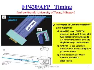
GASTOF Cherenkov Schematic of the GASTOF Cherenkov ant its intrinsic time resolution. Depicted from the FP420 R&D Project
GASTOF Cherenkov with RF phototube Schematic of the GASTOF Cherenkov with RF phototube
Readout Electronics Schematic of the Readout Scheme with Multi Pixel Anode The expected at maximum luminosity 10 MHz rate the RF deflector is distributed among ~100 pixels. Each pixel will operate as an independent PMT with ~0.1 MHz rate. 26
Conclusion GASTOF with Radio Frequency Phototube Intrinsic Time resolution few ps Rate 10 MHz Stability < 1 ps/hrs Ability to detect several ten events in a ns period 27