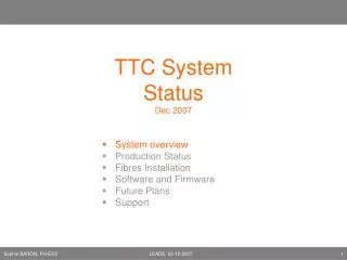
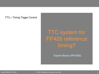
TTC system for FP420 reference timing?
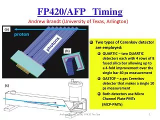
TTC system for FP420 reference timing?. TTC = Timing Trigger Control. Sophie Baron (PH-ESS). FP420 requirements for timing transmission. Bunch Clock and Orbit(?) to be transmitted Level of radiations = ?? Clock monitoring between the 2 signals

TTC system for FP420 reference timing?
E N D
Presentation Transcript
TTC system for FP420 reference timing? TTC = Timing Trigger Control Sophie Baron (PH-ESS) FP420 Collaboration meeting, Sept. 2006
FP420 requirements for timing transmission • Bunch Clock and Orbit(?) to be transmitted • Level of radiations = ?? • Clock monitoring between the 2 signals • 10 ps rms jitter skew between the clocks in W and E FP420 Collaboration meeting, Sept. 2006
Existing system • The TTC system • Rad-hard chips • Monitoring the phase between 2 optical signals • Various transmission schemes used by the TTC system • Typical jitter values FP420 Collaboration meeting, Sept. 2006
TTC system in one slide …and a lot of various components and modules… Transmission of… • Timing of the LHC from the RF source to the experiments • LHC Bunch Clock (40.078xx MHz) • Revolution Frequency (11.245x kHz) Then combined inside the experiments with … • TriggerandControlsignals • Used by front-end electronics and readout systems …Using single optical fibres… FP420 Collaboration meeting, Sept. 2006
Radiation hard components • TTCrx: • 50ps rms • The TTCrx is now fabricated in the radiation-hard DMILL technology, which completely eliminates the possibility of a single-event latch-up, and should show a high immunity to single-event upset (SEU). • Tested up to : 8 Mrad (X-Rays) and – 5 x10¹³ n/cm2 (Neutrons) • QPLL: • 10-15ps rms • Tested up to 10Mrad (Co-60 γ) + 3 1015 n/cm2 • TRR receiver: • Optical receiver from Truelight (Taiwan) selected for most of the TTC designs • Tested with the TTCrx at the same doses. • OK if the optical power level stays above -20dBm (0.1mW) • Optical Fibers: • sensitive to radiations (attenuation increases with the dose) • Special fibres validated for ATLAS and CMS at high radiation levels (1014-1015 n cm-2 and total dose of 100 to 300 kGy) • Radiation hardness of multi-mode optical fibres for the ATLAS detector readout (June 1999,DG Charlton et all) FP420 Collaboration meeting, Sept. 2006
Clock differences Monitoring? Comparator control • Phase shift with temperature: • Typical value: shift of 25ps/degC/km • FP420 => 12ps/C per side if 420m on each side • Limit of the measurement: • The jitter between the W and E zones can not be monitored, as it is manly generated by the electronics doing the optical to electrical conversion • The measurement will only concern the phase shift between the 2 segments FP420 Collaboration meeting, Sept. 2006
Transmission Schemes • Encoded • TTC inside the experiments (based on aTTCrx chip) • Advantage: Allows to encode the orbit signal (and control frames) to the 40.078MHz • Drawback: jitter increases with the quantities of encoded data • QPLL added to reduce the jitter of the recovered clock down to 10-15ps rms • Parallel • TTC backbone system • Orbit and clock on separate fibres • Advantage: very low jitter after the opto-electrical conversion (10ps) without using the QPLL FP420 Collaboration meeting, Sept. 2006
Encoded Scheme [1] B* A 40MHz Clock TDM Encoder A B A B A B A B A B + BPM 25ns A Orbit B* (Idle) 0 0 0 1 0 1 1 1 • Used to transmit Timing, Trigger and Control inside the experiments • Serial transmission • 2 Channels are transmitted • A Channel: • Broadcasting Orbit (or L1a in experiments) • Low latency • Time critical signals • B Channel: • Framed & formatted commands and data (Hamming) • Broadcast or individually addressed • Internally used in the experiments • A & B are Time Division Multiplexed • BiPhase Mark encoding is used at 160.316Mbaud: balanced signal FP420 Collaboration meeting, Sept. 2006
Encoded Scheme [2] 50ps rms cy2cy Decoded CH. A Recovered Clock Clock TTCrx TRR QPLL Decoded CH. B Encoder & laser tx Photodiode, decoder & clock recovery Encoded Clock, A, B TTCrq CH. A (pulse, Orbit or trigger) CH. B (serial data frame) 40MHz Clock TTCex 15ps rms cy2cy FP420 Collaboration meeting, Sept. 2006
Parallel Scheme Clock and orbit on parallel fibres RF signal transmission scheme Laser Types OCP03: 300 $ OCP Tx 24: 600 $ Picture RF_Tx_D Picture RF_Rx_D Tx Board Rx Board • Photodiode Types • OCP Rx 03: 230 $ • OCP Rx 24: 300 $ • TRR: 8 CHF! FP420 Collaboration meeting, Sept. 2006
Typical Jitter values – Parallel Scheme [1] Comparator control C1 OCP Tx 03 C3 C2 TRR-1B43 + fanout +ECL driver TRR-1B43 + fanout +ECL driver C1/C3 12.4ps C2/C3 6.5ps C1/C2 12.4ps Lecroy Wavepro 7100 1GHz FP420 Collaboration meeting, Sept. 2006
Typical Jitter values – Parallel Scheme [2] Comparator control C1 OCP Tx 03 C3 C2 OCP Rx 03 + fanout +ECL driver OCP Rx 03 + fanout +ECL driver C1/C3 11.4ps C2/C3 4.0ps C1/C2 11.5ps Lecroy Wavepro 7100 1GHz FP420 Collaboration meeting, Sept. 2006