Download
1 / 24
250 likes | 450 Vues
Logical Effort A Method to Optimize Circuit Topology. Swarthmore College E77 VLSI Design Adem Kader David Luong Mark Piper December 6, 2005. Current Issues Facing Circuit Designers. Wanting to optimize circuits for faster performance, inexperienced designers often encounter…

E N D
Logical EffortA Method to Optimize Circuit Topology Swarthmore College E77 VLSI Design Adem Kader David Luong Mark Piper December 6, 2005
Current Issues Facing Circuit Designers • Wanting to optimize circuits for faster performance, inexperienced designers often encounter… • “Simulate-and-Tweak” loops • Incomplete intuition in design process • Uncertainty in decision-making
Logical Effort as a Solution • Quick method of circuit analysis • Circuit topology • Transistor sizing • Delay estimation • Easy way to compare multi-stage designs • “Back-of-the-envelope” calculation • Provides intuition of circuit timing characteristics in complex circuitry
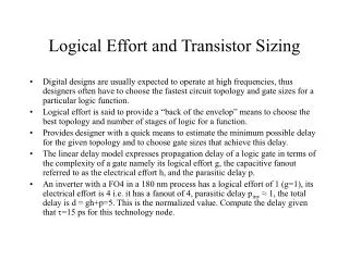
How does it work? • Assumes RC model of a transistor d = gh + p d = propagation delay gh = effort delay • g = logical effort • h = electrical effort = Cout/Cin p = parasitic delay
Defining Logical Effort • Ratio of the input capacitance of the gate to the input capacitance of an inverter that can deliver the same output current • Measure of a gate to drive a particular fan-out relative to an inverter
Application of Logical EffortEstimating Delay Propagation INVERTER d = g h + p NAND
Multi-Stage Design and Logical Effort • Often circuits are more complicated than an inverter or a NAND gate • Same framework applies with the modification…
Logical Effort and Transistor Sizing • Interested in choosing transistor sizing to minimize stage and overall delay f (min) = g(i) * h(i) = F1/N • Delay equation becomes… • In the end…
Application of Transistor Sizing How do we choose stage capacitances given we want to minimize propagation delay?
Optimal Number of Gates Rule of thumb is … Note that single gate does not always translate to minimized delay
Example: The Implementation Problem Which do you choose?
Using Logical Effort… • Option 1: • Path logic effort G = 1 * 6/3 * 1 = 2 • Path Branch Effort B = 1 • Path electrical effort H = Cout/Cin = 8C/C = 8 • Path Stage effort = F = GBH = 2*1*8 = 16 • Dmin = N*F1/N+P = 3*(16)1/3 + (1+4*1 + 1) = 3*3.25 + 6 = 13.5
Using Logical Effort… • Option 2: • Path logic effort G = 1 * 4/3 * 5/3 = 20/9 • Path Branch Effort B = 1 • Path electrical effort H = Cout/Cin = 8C/C = 8 • Path Stage effort = F = GBH = 20/9*1*8 = 160/9 • Dmin = N*F1/N+P = 3*(160/9)1/3 + (1+2*1 + 2) = 3*3.25 + 5 = 12.8
Example: Choosing the Optimal NThe Buffer Problem • Must drive 64 parallel inverters • Choose 1, 3, or 5 series inverter stages to drive the load?
Problems with logical effort • It’s only an approximation • But a good one • It does not guarantee optimal solution • but gets quite close • Chicken and egg problem • chicken • Built for speed • Does not account for power consumption and physical size
So What Have We Learned? • Logical Effort… • Provides method to quickly determine speed of design topologies for comparison • Displays changes to parameter tweaking
It’s so… logical! now that makes sense! I agree with stupid