ELC-213 Instrumentation
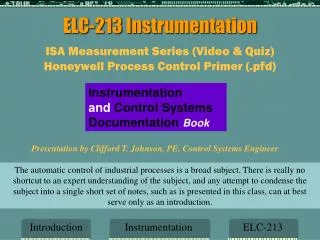
ELC-213 Instrumentation. ISA Measurement Series (Video & Quiz) Honeywell Process Control Primer (.pfd). Instrumentation and Control Systems Documentation Book. Presentation by Clifford T. Johnson, PE, Control Systems Engineer.

ELC-213 Instrumentation
E N D
Presentation Transcript
ELC-213 Instrumentation ISA Measurement Series (Video & Quiz) Honeywell Process Control Primer (.pfd) Instrumentation and Control Systems Documentation Book Presentation by Clifford T. Johnson, PE, Control Systems Engineer The automatic control of industrial processes is a broad subject. There is really no shortcut to an expert understanding of the subject, and any attempt to condense the subject into a single short set of notes, such as is presented in this class, can at best serve only as an introduction. Introduction Instrumentation ELC-213
Introduction to ICSD The purpose of the book and this class is to provide you with enough information that you will be able to understand the several documents that are associated and used by Instrument technicians and engineers working with Process Control Systems INSTRUMENT: as defined in ISA-5-1, is a device used for direct or indirect measurement, monitoring, and/or control of a variable, including primary elements, indicators, controllers, final control elements, computing devices and electrical devices such as annunciators, switches, and push buttons. Description Intro ELC-213
Introduction to ICSD cont INSTRUMENTATION: as defined in ISA-5.2, is a collection of instruments, devices, hardware or functions, or there applications for the purpose of measuring, monitoring or controlling an industrial process or machine, or any combination them. PROCESS CONTROL: as defined in the ISA dictionary, is the regulation or manipulation of the variables that influence the conduct of a process in such a way as to obtain a product of desired quality and quantity in a efficient manner SYSTEM: is the complex of hardware and software that is used to effect the control process Description Intro ELC-213
Types of Process Control Systems Continuous:Material is fed into and removed from the process without stopping • Steam Production • Waste Treatment • Distillation • Paper Making Batch:Material is added in steps that may require stopping and starting the processing requiring a recipe similar to baking a cake Discrete: Separate components, parts or sub-assemblies are added together to make a product similar to automotive manufacturing Introduction Processes ELC-213
Process Flow Diagram (PFD) A Process Flow Diagram - PFD - (or System Flow Diagram - SFD) shows the relationships between the major components in the system. PFD also tabulate process design values for the components in different operating modes, typical minimum, normal and maximum. A PFD does not show minor components, piping systems, piping ratings and designations. Including: Process Piping Major equipment symbols, names and identification numbers Control, valves and valves that affect operation of the system Interconnection with other systems Major bypass and recirculation lines Minimum, normal and maximum Process Parameters. Composition of fluids Description PFD ELC-213
Process Flow Diagram (PFD) Description PFD ELC-213
Piping & InstrumentDrawing The Piping (sometimes referred to as Process) andInstrumentation Drawing (P&ID) is the overall design document for a process plant. It defines, using symbols and word descriptions, the equipment, piping, and the instrumentation and control system. It is also the key to other documents. For example instrument tag numbers are shown on a P&ID. This tag number is the key to finding additional information about this device on many other documents. The same is true for line and equipment numbers. Description P&ID ELC-213
Piping & InstrumentDrawing Software connections Pneumatic connections Electric connections Capillary tube Shared Display Field Device Drawing P&ID ELC-213
Instrument Index (list) The Instrument List is an alphanumeric list of the data related to a facility's instrumentation and control systems components and, possibly, functions. Instrument Lists are organized using the alphanumeric tag numbers of the instrumentation and control system devices. They reference the various documents that contain the information needed to define the total installation. Description Instr Index ELC-213
Instrument Index (list) example Actual Instr Index ELC-213
Specification Sheets The Specification Forms or instrument data sheets define each tag-numbered instrumentation and control system device--with sufficient detail so a supplier can quote and eventually furnish the device. The Instrument person fills out the form EXCEPTfor the manufacture model number. The MFR should enter the information on the form that fills the requirements for the instrument. The Instrument person must obtain much of the information to complete the form from the Process or Chemical personnel Description Specifications ELC-213
Spec Sheets (forms) Actual Specification ELC-213
Logic Diagrams (drawings) Logic Diagrams are the drawings used to design and define the on-off or sequential part of a continuous process plant. For a typical Logic Diagram Description Logic Diagram ELC-213
Loop Diagrams (drawings) A Loop Diagram (commonly called loop sheet)is a schematic representation of a single control loop (sensing element, control component, and final element). It depicts the process connections and the components interconnection to the power sources and transmission systems (pneumatic, electronic, or digital). It is to the instrument person what an electrical elementary is to an electrician. All control devices that carry the number in their tag plus the devices that they operate and shown on a single 11X17” drawing, then placed in a book arranged by the loop NUMBER. They are a must for troubleshooting. Description Loop Sheets ELC-213
Loop Diagrams (drawings) Actual Loop Sheet ELC-213
Installation Details (drawings) Installation Details are used to show how an individual instrument component is connected. They show every piece of piping, fittings, cable and parts required by the contractor to install it. They do include a parts list to allow a contractor to develop a firm proposal to minimize change orders that can and often do increase cost of installations significantly. NOTE: They are not the same as Location Drawings that do show the routing of conduit between instrument devices, junction boxes, I/O panels and control rooms Description Installation ELC-213
Installation Details (drawings) Actual Installation ELC-213
Location Drawings Location Drawings (sometime referred to as Plans) are orthographic views of the plant, drawn to scale, that show the locations of instruments and control system components. They often show other control system hardware including marshaling panels, termination racks, local control panels, junction boxes, instrument racks, and perhaps power panels and motor control centers. They are the drawing that shows conduit and piping runs in the plant Description Location ELC-213
Location Drawings example Actual Location Diagram ELC-213
Honeywell Process Control Primer The type of control to be discussed is the kind involved in the so-called “Process Industries”, such as chemicals, petroleum, metals, paper, textiles, food, and water/waste water management. Examples are the refining of crude oil into fuel oils and gasoline; the conversion of wood pulp into paper; the extraction of metals from ores; the heat treating of metals; the production of glass; and the processing of municipal and industrial water supplies. The Modes of Control, (PID: Proportional, Integral & Derivative), will be dealt with Many times through out this course. Description Honeywell ELC-213
Calibration Typically, calibration of an instrument is checked at five (5) points throughout the calibration range of the instrument. The calibration range is defined as “the region between the limits within which a quantity is measured, received or transmitted and expressed by stating the Lower Range Value (LRV) and the Upper Range Value (URV).” The limits are defined by the zero and span values. The zero value is the low end of the range. Span is the algebraic difference between the URV and LRV. The calibration range may differ from the actual instrument range, which is the capability of the instrument. You will perform an actual calibration of a PT and I/P in the lab on real instruments Description Calibration ELC-213
Calibration PrinciplesCalibration Procedure are two pdf. files that you should study before attempting to calibrate the lab instruments later in the class Calibration is probably the most important, most critical, and most frequently performed of all seven domains for each of the three levels of certification required to become an ISA certified Technician. Anyone interested in becoming certified contact me You will perform an actual calibration of a Pressure Transmitter and I/P Transducer in the lab on real instruments Description Calibration ELC-213
Fieldbus Fieldbus provides two-way, multi-drop digital communication between devices on the plant floor as well as the automation and display systems. Thus, Fieldbus is essentially a Local Area Network (LAN) for field devices. Not recommended for the faint of heart Fieldbus Process Plant P Automation and Display Systems L F Description Fieldbus ELC-213
PC-ControlLab The last Lab will require you to use a computer Simulator. You will TUNE the Simulator on a Pressure, Temperature and Flow control Process Description Fieldbus ELC-213
TODAYS ASSIGNMENT, Lab & Video Process Flow Diagrams (PFD) Temperature Measurement & Quiz All Assignments Must be Emailed to me by the Sunday following class, The bolded words are the subjects to be used for your email Subject and Lab file names Today Assignment & Lab ELC-213
LAB Resources CPCC.CTJohnson.com/Resources Click on the X for the file type you want and download it templates Resources ELC-213
LAB Requirements for drawings This course will introduce you to the types of drawings. Since many of you can’t use CAD, I have created the drawings for you to download from my web site, Then you can complete them in a AutoCAD, Visio, Libre Open Office Draw and email to me . The pdf. file is only for reference. Be sure you rename the file correctly: Last Name-Subject-Assignment date (.xxx) .pdf file (referrence only) .dwg for AutoCAD, Be sure to same as Version 12 or .dxf file .vsd for Visio, Should be on computers on 2nd floor .odg for Open Offic, you can actually edit Visio files with Libre Open Office draw (Apache Open Office draw will not work) Lab Requirements ELC-213
LAB for this week This weeks Lab requires you to download the PFD (Process Flow Diagram) and fill in the Title block, information block, and complete the the drawing. Bear in mind: you lose points if a document does not include and the file name is not correct your Last name-Subject-Date The date must be the ASSIGNMENT date, not the date that you actually complete the lab, nor the date that you email it to me. Be sure to include the Information block: The water flow stream pump output is number 2, the pump output is 0-10 GPM, cold water, ambient temp, 30 ft head pressure, specific gravity???? This weeks Requirements ELC-213
PFD (Process Flow Diagram) Assignment date Your Initials Drawing is not complete, you must add information to complete it Your name Information Block goes in this space See text book for more information PFD Typical Drawing ELC-213
PFD to download Be sure to identify all devices on drawing per the drawing ( fig 1-1) example in the book and fill in the information block per the assignment Be sure to remove instructions or you will lose a point PFD Download Drawing ELC-213
TEMPERATURE Measurement Video & Quiz ISA (International Society for Automation) {formally the Instrument Society of America 1st in a series of four Measurement videos Temperature Measurements The first four classes the quiz will be on the one hour measurement series video. Then the student must download the .pdf file from the web site and answer the 10 questions at the end of the file. Email the answers in the body of the email to me by Sunday. If I don’t have them the day before the next weeks class you may get “0” points. Description Videos & Quiz ELC-213
ASSIGNMENT & LAB DUE Dates All Assignments, Labs & Measurement video Quizzes are due no later than the day before next weeks class, If I don’t have the lab work you may be shown absent for Lab of previous week Grades are based on a point system: • Quiz = 10 points (9 points = 100%) • Homework Assignment (Web Link) = 6 points • Lab work= 10 points • Final Exam = 10 Points Late assignments or labs are subject to lose of all points unless there is an acceptable excuse Due Dates & Points ELC-213
Homework ASSIGNMENT Web Link Find an example of a temperature indicator; transmitter; controller; or thermostat on the web, email web LINK only in body of email to me, Do Not Use Google Images the link must include information Email subjects and file names must be the same except for .xxx of file name Subject:Yourlast Name-Subject-AssignmentDate Email link subject Ex:Johnson-Temperature-8/20/14 Lab file name & email subject Ex:Johnson-PFD-8/20/14 You will lose 1-3 points for incorrect subject Subject Assignment & Lab ELC-213
My Email Address cliff.johnson@cpcc.edu Important: DOemail or call me if you are going to be tardy or miss class, if you don’t you may not be able to make up the quiz.Labs & Homework are still required by due date Celphone: 980-939-5184 BTW: you have an opportunity to correct LAB errors only if you email it by Friday so I can return it with comments and grade. Email Address ELC-213
The End The first state of the art Distributed Control System (DCS) designed by Cliff Johnson and installed in a Pulp & Paper plant in 1980 End Instrumentation ELC-213