Topics Basic Capacitor Types of Capacitors Parallel Capacitors Capacitors in DC Circuits
Topics Basic Capacitor Types of Capacitors Parallel Capacitors Capacitors in DC Circuits Capacitors in AC Circuits Capacitor Applications. Conductors. The Basic Capacitor. Capacitor:

Topics Basic Capacitor Types of Capacitors Parallel Capacitors Capacitors in DC Circuits
E N D
Presentation Transcript
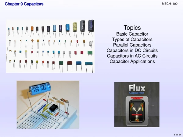
Topics Basic Capacitor Types of Capacitors Parallel Capacitors Capacitors in DC Circuits Capacitors in AC Circuits Capacitor Applications
Conductors The Basic Capacitor • Capacitor: • Electrical device composed of two parallel conductive plates separated by an insulating material(dielectric). • The ability to store charge is the definition of capacitance. Dielectric
Initially uncharged Source removed Fully charged Charging The Basic Capacitor The charging process… A capacitor with stored charge can act as a temporary battery.
Capacitance Capacitance is the ratio of charge to voltage C = Capacitance (ability to store charge) Q = Charge (coulombs) V = Volts
Capacitance • Capacitance (farad) • Farad • Amount of capacitance when one coulomb of charge is stored with one volt across the plates. The amount of charge on a capacitor is determined by the size of the capacitor (C) and the voltage (V). If a 22 mF capacitor is connected to a 10 V source, the charge is 220 mC
Energy Storage A capacitor stores energy in the form of an electric field that is established by the opposite charges on the two plates. The energy of a charged capacitor is given by the equation where W = the energy in joules C = the capacitance in farads V = the voltage in volts
Electrical Characteristics Voltage rating – amount of voltage that can be withstood across the plates Breakdown or working voltage - voltage at which physical damage is done to the capacitor. Dielectric strength – A measure of a compounds ability to serve as an insulator. V/mil (.001” or 2.54 * 10-5 meter) See Table 9-2 – Page 392 Temperature coefficient – indicates the amount and direction of change in capacitance value with temperature Leakage – amount of charge that leaks through the dielectric
Physical Characteristics Plate area – Capacitance is directly proportional to the plate area. Plate separation – Capacitance is inversely proportional to the distance between the plates.
Dielectric constant (or relative permittivity) – measure of a material’s ability to establish an electric field. Capacitance is directly proportional to the dielectric constant.
Dielectric constant (or relative permittivity) – measure of a material’s ability to establish an electric field. Capacitance is directly proportional to the dielectric constant. Absolute permittivity of a vacuum = (epsilon) A= area in meters2 d = meters c = farads Capacitance
Capacitor types Mica - very hard, heat resistant mineral Mica capacitors are small with high working voltage. er (5)
Capacitor types Ceramic disk Ceramic disks are small non-polarized capacitors They have relatively high capacitance due to high er (1200)
Capacitor types Plastic Film Plastic film capacitors are small and non-polarized. They have relatively high capacitance due to larger plate area.er (depends on the film used)
Capacitor types Electrolytic (two types) • Electrolytic capacitors have very high capacitance • not as precise as other types and • tend to have more leakage current. • Electrolytic capacitors are the only ones polarized. Aluminum electrolytic Tantalum electrolytic Symbol for any electrolytic capacitor
Defibrillator Capacitor can deliver over 500 joules of energy Power Factor Correction
Capacitor types Variable • Variable capacitors: • have small capacitance values and • are adjusted manually • called Trimmers, padders or tuning capacitors because they are used to make very fine adjustments in a circuit. • Varactor diode - A semiconductor that exhibits capacitive characteristic; it is adjusted with an electrical signal.
Capacitor labeling Small capacitors values are frequently stamped on them such as .001 or .01, which have implied units of microfarads. Electrolytic capacitors have larger values, so are read as mF. Usually stamped as mF, but some older ones may be shown as MF or MMF).
Capacitors in series • Divide Voltage across them in proportion to their capacitance • Current is same at all points while charging; then goes to zero Q is charge and C is capacitance
Series capacitors When connected in series, the total capacitance is smaller than the smallest one. Capacitance for any number of capacitors in series Capacitance for two capacitors in series
Series capacitors If a 0.001 mF capacitor is connected in series with an 800 pF capacitor, the total capacitance is 444 pF 1000pF
Voltage in Series Capacitors • Voltage depends on capacitance value • Smallest value capacitor will have the largest voltage across it • Largest value capacitor will have the smallest voltage across it.
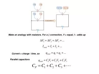
Parallel capacitors When capacitors are connected in parallel, the total capacitance is the sum of the individual capacitors. The voltage across capacitors is the same in each parallel branch. The total charge stored by each capacitor is proportional to its capacitance. QT=Q1+Q2+Q3+…+QN VC2 = VC1 VC2 = VC1
If a 0.001 mF capacitor is connected in parallel with an 800 pF capacitor, the total capacitance is Parallel capacitors The general equation for capacitors in parallel is 1800 pF
Capacitors in DC Circuits A capacitor charges when connected to a DC voltage. When fully charged, there is no current flow. Except for leakage, a capacitor will remain charged for long periods. A capacitor appears as an “open” to a constant voltage. A capacitor appears as a “short” to an instantaneous change in voltage. When discharging the flow of current is in the opposite direction from the charging cycle.
The RC time constant • RC Time Constant: • A fixed time interval that equals the product of the resistance and the capacitance in a series capacitor circuit.
The RC time constant When a capacitor is charged through a series resistor and dc source, the charging curve is exponential.
The RC time constant When a capacitor is discharged through a resistor, the discharge curve is also an exponential. (Note that the current is negative.)
Universal exponential curves • The general voltage formula is • v =VF + (Vi - VF)e-t/RC • VF = final value of voltage • Vi = initial value of voltage • v = instantaneous value of voltage • The final capacitor voltage is: • greater than the initial voltage when the capacitor is charging, or • less than the initial voltage when it is discharging.
Rising (charging) exponential Universal exponential curves Specific values for current and voltage can be read from a universal curve. For an RC circuit, the time constant is Falling (discharging) exponential Any capacitor will charge in 5 time constants!!
Universal exponential curves Example How long will it take to charge the capacitor shown in the circuit below to 16 volts? Use the charging curve shown. 20v 16 volts = 80% of final value 80% (16 v) of charge occurs at ~ 1.6 time constants τ = (10*103Ω)*(.001x10-6F) = 10 x10-6 sec = 10µs ∴ Time to reach 16v = 1.6 x 10µs ~ 16 µs Time to reach 17.2 volts?
Capacitors in AC Circuits • When the source voltage is held at a constant amplitude and the frequency is: • increased the amplitude of the current increases which indicates a decrease in resistance to charging. • decreased the amplitude of the current decreases which indicates an increase in resistance to charging
Capacitive Reactance • The opposition to ac by a capacitor is known as Capacitive reactance (XC). Unit is Ohms • Capacitive reactance is: • inversely proportional to frequency • inversely proportional to capacitance f – hertz C - farads The capacitive reactance of a 0.047 mF capacitor when a frequency of 15 kHz is applied is 226 W
Reactance for Series Capacitors When capacitors are in series, the total capacitive reactance is the sum of the individual reactance's. Assume three 0.033 mF capacitors are in series with a 2.5 kHz ac source. What is the total reactance? The reactance of each capacitor is 5.79 kW
Reactance for Parallel Capacitors When capacitors are in parallel, the total reactance is the reciprocal of the sum of the reciprocals of the individual reactance's. If the three 0.033 mF capacitors from the last example are placed in parallel with the 2.5 kHz ac source, what is the total reactance? The reactance of each capacitor is 1.93 kW 643 W
Ohms Law for Capacitors The capacitive reactance of a capacitor is the same as a resistor Xc same as resistance Current and volts must be in the same units but it does matter which (i.e. rms, peak, p to p) Calculate I 7957.7Ω Irms= 2vrms/7957.7Ω = 0.25mA
Capacitive Voltage Divider • Two capacitors in series are used as a capacitive voltage divider. • The capacitors split the output voltage: • in proportion to their reactance and • inversely proportional to their capacitance. XCX is the reactance of the capacitor CX XC(tot) – total capacitive reactance VX – voltage across capacitor CX Vout
Capacitive Voltage Divider What is the output voltage for the capacitive voltage divider? Vout 91 mV
Capacitive Voltage Divider Two capacitors in series are commonly used as a capacitive voltage divider. The capacitors split the output voltage in proportion to their reactance (and inversely proportional to their capacitance). Example What is the output voltage for the capacitive voltage divider? Solution: Vout 91 mV
Capacitive Voltage Divider Instead of using a ratio of reactances in the capacitor voltage divider equation, you can use a ratio of the total series capacitance to the output capacitance (multiplied by the input voltage). The result is the same. For the problem presented in the last slide, 91 mV Vout
Capacitive phase shift When a sine wave is applied to a capacitor, there is a phase shift between voltage and current such that current always leads the voltage by 90o.
Power in a capacitor Energy is stored by the capacitor during a portion of the ac cycle and returned to the source during another portion of the cycle. Power is maximum where the V and I curves cross
Power in a capacitor Voltage and current are always 90o out of phase. No true power is dissipated by a capacitor, because stored energy is returned to the circuit. The rate at which a capacitor stores or returns energy is called reactive power. The unit for reactive power is the VAR (volt-ampere reactive).
Rectifiers Convert a sinusoidal wave (ac) to a pulsing dc wave
Rectifier C Load resistance 60 Hz ac Power supply filtering Pulsing voltage and current are not usually desirable for operating equipment A capacitor adds a smoothing effect to the wave by discharging on the down slope of the curve. The filter smoothes the pulsating dc from the rectifier.
Key Terms Capacitor Dielectric Farad RC time constant An electrical device consisting of two conductive plates separated by an insulating material and possessing the property of capacitance. The insulating material between the conductive plates of a capacitor. The unit of capacitance. A fixed time interval set by the R and C values, that determine the time response of a series RC circuit. It equals the product of the resistance and the capacitance.
Key Terms The opposition of a capacitor to sinusoidal current. The unit is the ohm. Capacitive reactance Instantaneous power (p) True power (Ptrue) Reactive power (Pr ) VAR (volt-ampere reactive) The value of power in a circuit at a given instant of time. The power that is dissipated in a circuit usually in the form of heat. The rate at which energy is alternately stored and returned to the source by a capacitor. The unit is the VAR. The unit of reactive power.
Quiz 1. The capacitance of a capacitor will be larger if a. the spacing between the plates is increased. b. air replaces oil as the dielectric. c. the area of the plates is increased. d. all of the above.