Microcontroller Basics
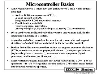
Microcontroller Basics. A microcontroller is a small, low-cost computer-on-a-chip which usually includes: An 8 or 16 bit microprocessor (CPU). A small amount of RAM. Programmable ROM and/or flash memory. Parallel and/or serial I/O. Timers and signal generators.

Microcontroller Basics
E N D
Presentation Transcript
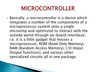
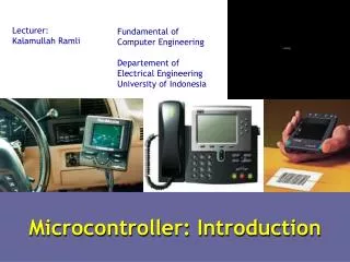
Microcontroller Basics • A microcontroller is a small, low-cost computer-on-a-chip which usually includes: • An 8 or 16 bit microprocessor (CPU). • A small amount of RAM. • Programmable ROM and/or flash memory. • Parallel and/or serial I/O. • Timers and signal generators. • Analog to Digital (A/D) and/or Digital to Analog (D/A) conversion. • Often used to run dedicated code that controls one or more tasks in the operation of a device or a system. • Also called embedded controllers, because the microcontroller and support circuits are often built into, or embedded in, the devices they control. • Devices that utilize microcontrollers include car engines, consumer electronics (VCRs, microwaves, cameras, pagers, cell phones .. ), computer peripherals (keyboards, printers, modems.. ), test/measurement equipment (signal generators, multimeters, oscilloscopes …). • Microcontrollers usually must have low-power requirements (~. 05 - 1 W as opposed to ~10 - 50 W for general purpose desktop CPUs) since many devices they control are battery-operated.
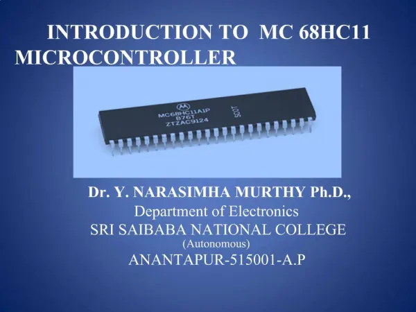
From sensors To actuators Displays, keyboard etc. RAM, EPROM, EEPROM, flash Single Chip Microcontroller Components Examples: Motorola’s 68HC11, 68HC12, AMD 29K, Zilog’s Z8, Z80, Intel’s 8052, Microchip’s PIC Low-power, embedded versions of desktop CPUs: e.g Intel’s 80486
A Typical Microcontroller Application:Car Cruise Control Speed Measurement
The Motorola 68HC12 Microcontroller A Typical 68HC12 has the following components on the chip: • A 16-bit central processing unit (CPU12): • 20-Bit ALU. Instruction Queue. • Enhanced Indexed Addressing. Fuzzy Logic Instructions. • 32-Kbyte Flash EEPROM with 2-Kbyte Erase-Protected Boot Block. • 768-Byte EEPROM. • 1-Kbyte RAM with Single-Cycle Access for Aligned or Misaligned Read/Write. • 8-Channel, 8-Bit Analog-to-Digital (A/D) Converter. • 8-Channel Timer. • 16-Bit Pulse Accumulator: • External Event Counting, Gated Time Accumulation. • Pulse-Width Modulator: • 8-Bit, 4-Channel or 16-Bit, 2-Channel • Separate Control for Each Pulse Width and Duty Cycle
A Typical 68HC12 Chip Pin-Out MC68HC912B32
0x0800 User Program Memory: 256 bytes 0x08FF 0x0900 User Data Memory: 256 bytes 0x09FF Motorola 68HC12 16-bit Memory Address Space
68HC12 Registers A 8-bit Accumulator A B 8-bit Accumulator B D 16-bit Double accumulator D (A : B) X 16-bit Index register X Y 16-bit Index register Y SP 16-bit Stack pointer PC 16-bit Program Counter CCR Condition code register: S STOP instruction control bit X Non-maskable interrupt control bit H Half-carry status bit I Maskable interrupt control bit N Negative status bit Z Zero status bit V Two’s complement overflow status bit C Carry/Borrow status bit
68HC12 Data Types The HC12 uses the following types of data: • Bits. • 5-bit signed integers. • 8-bit signed and unsigned integers. • 8-bit, 2-digit binary coded decimal (BCD) numbers. • 9-bit signed integers. • 16-bit signed and unsigned integers. • 16-bit effective addresses. • 32-bit signed and unsigned integers. • 5-bit and 9-bit signed integers are used only as offsets for indexed addressing modes. • 16-bit effective addresses are formed during addressing mode computations. • 32-bit integer dividends are used by extended division instructions. • Extended multiply and extended multiply-and-accumulate instructions produce 32-bit products.
68HC12 Addressing Modes • Inherent Addressing Mode (INH). • Immediate Addressing Mode (IMM). • Direct Addressing Mode (DIR). • Extended Addressing Mode (EXT). • Indexed Addressing Modes: • 5-Bit Constant Offset Indexed Addressing (IDX). • Auto Pre/Post Decrement/Increment Indexed Addressing (IDX) • Accumulator Offset Indexed Addressing (IDX). • 9-Bit Constant Offset Indexed Addressing (IDX1). • 16-Bit Constant Offset Indexed Addressing (IDX2). • Indirect Indexed Addressing: • 16-Bit Constant Offset Indexed Addressing [IDX2]. • Accumulator D Indirect Indexed Addressing [D, IDX].
68HC12 Addressing Modes • Inherent Addressing Mode (INH): • Instructions that use this addressing mode either have no operands or all operands are in internal CPU registers. • Examples: NOP ; this instruction has no operands CLRA ; clear A ABA ; add A to B result in A ASRA ; arithmetic shift right A • Immediate Addressing Mode (IMM): • Examples: LDAA #$55 ; load A with the 8-bit value $55 LDX #$1234 ; load index register X with 16-bit address $1234 LDY #$67 ; load index register Y with 16-bit address $0067 ADDA #$17 ; add the value $17 to register A, result in A
68HC12 Addressing Modes • Direct Addressing Mode (DIR): • Used to access operands in the memory address range $0000 through $00FF • Examples: LDAA $55 ; load register A with 8-bit value in memory address $0055 LDX $20 ; load index register X with 16-bit value in $0020, $0021 STY $50 ; store value of Y to memory addresses $0050, $0051 • Extended Addressing Mode (EXT): • Used to access operands in the full 16-bit address of the memory. • Examples: LDAA $F03B ; load register A with 8-bit value from address $F03B LDX $0900 ; load index register X with 16-bit value in $0900, $0901
68HC12 Indexed Addressing Modes • 5-Bit Constant Offset Indexed Addressing (IDX): • Uses an 5-bit signed offset (range -16 to 15) which is added to the base index register (X, Y, SP, or PC) to form the effective address: • Examples: LDAA 12,X ; load A with the byte at memory address (X) + 12 STAB –8,Y ; store the byte in B at address (Y) - 8 ADDA 5,X ; add A to the byte at (X) + 5, result in A • 9-Bit Constant Offset Indexed Addressing (IDX1): • Uses an 9-bit signed offset (range -256 to 255) which is added to the base index register (X, Y, SP, or PC) to form the effective address: • Examples: LDAA $FF,X ; load A with the byte at memory address (X) + $FF STAB –20,Y ; store the byte in B at address (Y) - 20 • 16-Bit Constant Offset Indexed Addressing (IDX2): • Uses an 16-bit offset which is added to the base index register (X, Y, SP, or PC) to form the effective address. • This allows access to any address in the 64-Kbyte address space.
Auto Pre/Post Decrement/Increment Indexed Addressing (IDX) • Predecrement and preincrement versions of the addressing mode adjust the value of the index register before accessing the memory location affected by the instruction: STAA 1,–SP ;equivalent to PSHA STX 2,–SP ;equivalent to PSHX • Post-decrement and postincrement versions of the addressing mode use the initial value in the index register to access the memory location affected by the instruction, then change the value of the index register. LDX 2,SP+ ;equivalent to PULX LDAA 1,SP+ ;equivalent to PULA
Indexed Addressing Modes Accumulator Offset Indexed Addressing (IDX): • In this indexed addressing mode, the effective address is the sum of the values in the base index register (X, Y, SP, or PC) and an unsigned offset in one of the accumulators (8bit A, B or 16-bit D). • Example: LDAA B,X • This instruction internally adds B to X to form the address from which A will be loaded.
Indirect Indexed Addressing • 16-Bit Constant Offset Indexed Addressing [IDX] : • Adds a 16-bit instruction-supplied offset to the base index register to form the address of a memory location that contains a pointer to the memory location affected by the instruction. • Example: LDAA [10,X] • In this example, X holds the base address of a table of pointers. • Assume that X has an initial value of $1000, and that the value $2000 is stored at addresses $100A and $100B. • The instruction first adds the value 10 to the value in X to form the address $100A. • Next, an address pointer ($2000) is fetched from memory at $100A. • Then, the byte value stored in location $2000 is read and loaded into the A accumulator.
Indirect Indexed Addressing • Accumulator D Indirect Indexed Addressing [D,IDX]: • Adds the value in the D accumulator to the value in the base index register to form the address of a memory location that contains a pointer to the memory location affected by the instruction. • The square brackets distinguish this addressing mode from D accumulator offset indexing. • Example: JMP [D,PC] GO1 DC.W PLACE1 GO2 DC.W PLACE2 GO3 DC.W PLACE3 • Assume that the value in D is $0002. • The JMP instruction adds the values in D and PC to form the address of GO2. • Next the CPU reads the address PLACE2 from memory at GO2 and jumps to PLACE2.
Multiply and Accumulate InstructionEMACS • The EMACS instruction multiplies two 16-bit operands stored in memory and accumulates the 32-bit result in a third memory location. • Often used to implement simple digital filters.
HC12 Short Branch Instructions The numeric range of short branch offset values is $80 (–128) to $7F (127)
HC12 Short Branch Instructions The numeric range of short branch offset values is $80 (–128) to $7F (127)
HC12 Long Branch Instructions The numeric range of long branch offset values is $8000 (–32,768) to $7FFF (32,767)
HC12 Long Branch Instructions The numeric range of long branch offset values is $8000 (–32,768) to $7FFF (32,767)
HC12 Example: Addition of Two Values USER_STACKTOP equ $0a00 org $0800 Main lds #USER_STACKTOP ;load stacktop ldaa #FIRST ;load first byte in A adda #SECOND ;add second value to A result in A staa ANSWER ;store result in answer End bra End ;done with program org $0900 FIRST dc.b #$01 ;first value to add SECOND dc.b #$02 ;second value to add ANSWER dc.b #$00 ;addition result
HC12 Loop Example USER_STACKTOP equ $0a00 org $0800 Main: lds #USER_STACKTOP ;load stacktop ldaa #ITER ;load number of iterations to perform ldab #COUNT ;load number of iterations performed already loop: deca ;decrement Acc A incb ;increment Acc B cmpa #$00 ;Is Acc A = 0? bne loop ;No, continue with loop stab COUNT ;Otherwise, save the count End: bra End ;done with program org $0900 ITER dc.b #$08 ;Number of loop iterations to perform COUNT dc.b #$00 ;Number of loop iterations performed
HC12 Data Table Example ; This program takes a table of data, and creates a new table ; which is the original table divided by 2 prog: equ $0800 ;put program at address 0x0800 data: equ $0900 ;put data at address 0x0900 count: equ 10 ;number of entries in table org prog ;set program counter to 0x0800 ldx #table1 ;Reg X points to entry to process in table 1 ldy #table2 ;Reg Y points to entry to write to table 2 ldab #count ;ACC B holds number of entries left to process repeat: ldaa 1,x+ ;Get table1 entry into ACC A; inc X to next entry asra ;Divide by 2 staa 1,y+ ;Save in table2; inc Y to next entry in table2 dbne b,repeat ;Decrement number left to process; ;If not done, process next table1 entry swi ;Done -- Exit org data ;initialize table1 (COUNT bytes long) table1: dc.b $07,$ae,$4a,$f3,$6c,$30,$7f,$12,$67,$cf table2: ds.b count ;reserve count bytes for table2.