Download
1 / 22
220 likes | 350 Vues
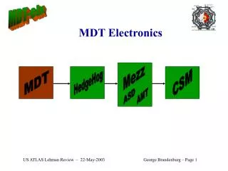
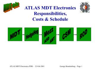
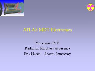
Production Testing of ATLAS MDT Front-End Electronics. G. Brandenburg, J. Oliver, M. Nudell, Harvard University, Cambridge MA C. Posch, E. Hazen , Boston University, Boston MA L. Kirsch, Brandeis University, Waltham MA. Monitored Drift Tube (MDT) System.

E N D
Production Testing of ATLAS MDT Front-End Electronics G. Brandenburg, J. Oliver, M. Nudell, Harvard University, Cambridge MA C. Posch, E. Hazen, Boston University, Boston MA L. Kirsch, Brandeis University, Waltham MA E. Hazen - LECC 2003 - Amsterdam
Monitored Drift Tube(MDT) System • Pressurized tubes: Ar/CO2 at 3 atm • 3cm Aluminum tubes, 50m Au-plated W-Re wire • Length to 6m • Z0 = 390 W • Gas gain ~ 2*104 • Maximum drift time ~ 700 ns • Resolution spec (per tube) 80 m • Total of 360k tubes E. Hazen - LECC 2003 - Amsterdam
MDT Chamber Chamber isolated electrically from support and services. Only power/optical connections LV Power TTC Fanout Drift Tubes LV Power 5V DC @ 60W Isolated Ground Spacer Frame Optical Fibers HV Power Drift Tubes HV Power 3.5kV Isolated Ground (1k) ROD (DAQ) Gigabit Optical Link (GOL) Chamber Service Module Single Point Earth Ground E. Hazen - LECC 2003 - Amsterdam
MDT Electronics Readout End Completely Shielded Drift Tubes Lower Faraday Cage Hedgehog PCB Upper Faraday Cage Mezzanine PCB E. Hazen - LECC 2003 - Amsterdam
1 of 8 channels Transimpedance preamps Signal Discriminator (delta response) Bipolar shaper LVDS Control logic Dummy Wilkinson ADC DACs Calibration Mode Deadtime Serial string register ASD Chip ZIN 120 TW QIN Note: with grateful acknowledgement of work of Mitch Newcomer / U.Penn E. Hazen - LECC 2003 - Amsterdam
AMT-3 TDC • 24 Channels • 0.78 ns least count • Trigger matching logic • LVDS serial I/O for control and data • CMOS; rad-tolerant E. Hazen - LECC 2003 - Amsterdam
Mezzanine Board Octal ASD Note 2D Barcode AMT-3 TDC Discharge Protection Power, I/O Connector Digital, Analog Voltage Regulators Top/Bottom Layer PCB Ground Planes E. Hazen - LECC 2003 - Amsterdam
Chamber Service Module • Multiplex up to 18 x 24 channels via optical fiber • JTAG control of front-ends • TTC (trigger/clock) signals distribution TTC Fiber Ribbon Cables From Mezz Boards CSM GOL Fiber To DAQ DC Power E. Hazen - LECC 2003 - Amsterdam
ASD Production • Packaged ICs purchased • 72k parts tested in 3 months on home-made automatic tester • 3-5 sec per chip test time (no robotic loader) • Tester cost about $100k including 1 m-yr University engineering (vs $500k for lower-performance commercial tester) • Detailed test results kept in database E. Hazen - LECC 2003 - Amsterdam
ASD Tester Overview • High-level commandsi.e.: • Read preamp input levels • Measure noise rate Controller FPGA (XC2V1000) Test Socket (daughter board) LVDS (Outputs) Input Fifo Commands Serial i/o DC PC Parallel Interface Output Fifo Analog support DACs, ADCs, Multiplexers Data Control • Command Processor: • 16ns clock period • 4ns TDC (DLL) • Floating-point timer (20Hz-20MHz) • High-level result datai.e.: • Measured DC levels • Measured noise rate E. Hazen - LECC 2003 - Amsterdam
ASD Tests • Serial I/O Test to verify JTAG interface • DC (voltage/current) tests: • Preamp input voltage (self-bias point) • Bias Voltage Generator sweep • Can extract KP and KN • LVDS Driver Output VDIFF and VCM • Power Supply Current • AC (dynamic) tests: • Wilkinson ADC parameters • Programmable deadtime vs setting • Threshold sweep • Vary discriminator threshold and measure noise hit rate • Fit results to Gaussian • Extract V(offset), Sigma and nose rate at threshold=0 • All results saved to database for long-term reference E. Hazen - LECC 2003 - Amsterdam
Threshold Sweep Test(Example of One Test) • Noise vs threshold sweep • Gaussian fit gives • Sigma • Discriminator offset voltage • Peak hit rate • Test takes ~2 sec • 2 channels simultaneously 4 seconds • Grand total test time < 5 seconds • This test is an effective “go/no-go” test of the entire analog chain. E. Hazen - LECC 2003 - Amsterdam
Threshold Sweep Test Implementation Loop over threshold Settings from –40 to 40mV (software loop) Measure time to record 32 hits using floating-point Timer (FPGA logic) Effective range from 20Hz to 20MHz Controlled by FSM Implemented using StateCADTM Floating- Point Timer Latch A MUX Data Out Latch B 8-bit mantissa 3-bit exponent OVFL OVFL Chan. A Counter Chan. B Counter 5-bit event counters Chan. A ASD output Chan. B ASD output Control Logic (State Machine) E. Hazen - LECC 2003 - Amsterdam
Channel-to-channel spread of DC offsets at discriminator is most useful output of this test Primary parameter for “quality” grouping of ASDs Threshold Sweep TestResults: Offsets Cut at 12mV Gives 75% yield E. Hazen - LECC 2003 - Amsterdam
ASD Test Result Summary • Overall 93% yield of functional parts • Most “Out of Tolerance” rejects due to threshold offsets > 12mV E. Hazen - LECC 2003 - Amsterdam
Board Production Plan • Assemble in Israel, ship to Boston • Test flow: • Serialize with 2D Barcodes • Burn-in (24hr at elevated temp) • Full Functional Test • Pack and Ship E. Hazen - LECC 2003 - Amsterdam
VME Readout PC, Software… Mezz Board Test Setup Readout Adapter Sites for 15 Boards Test Pulse Injector E. Hazen - LECC 2003 - Amsterdam
Mezz Board Testing • Full test of 15 boards in a few minutes • JTAG programming test • Threshold sweep similar to chip test • Termination resistor seen; confirms board connectivity • Verifies TDC and DAQ logic functionality • Bonus: • Individual boards can be identified with 99.999% accuracy by threshold offset “signature” E. Hazen - LECC 2003 - Amsterdam
Board Burn-In Facility • 24-hour elevated temp burn-in • Continuous monitoring of current, voltage, temp. Summary data stored indefinitely in database Enclosed Cabinet Rack PC with I/O Card (Digital/Analog) 10 Subracks (3U std) Power Supply E. Hazen - LECC 2003 - Amsterdam
Board Burn-In Data • “Strip Chart” record: • Temperature (each board) • Analog, Digital regulator output • Analog, Digital supply current • Problems such as tantalum cap failures show clearly • Max/Min/Mean/Sigma of each quantity stored in permanent database E. Hazen - LECC 2003 - Amsterdam
Database • Extensive set of measured parameters kept for each channel/chip/board • Web access with query/plot facilities • Tied to barcode ID of each chip and board • Some sample plots: Scatterplot of FET KN vs KP Histogram of Threshold Offsets E. Hazen - LECC 2003 - Amsterdam
Summary • Custom test hardware for production of 360k channels built • 72k chips tested in 3 months • Test/burn-in capacity of 150 boards/day • On track to start delivery later this year • Would we do it this way again? Yes! E. Hazen - LECC 2003 - Amsterdam