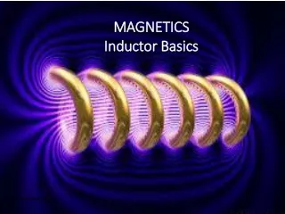
Inductor
Inductor. A circuit component designed for inductance is an inductor . Symbol suggests coiled wire Ideal inductors act like wires unless the current changes. Emf based on L Real inductors have some resistance. Resistivity of length of wire. Physical Coil.

Inductor
E N D
Presentation Transcript
A circuit component designed for inductance is an inductor. Symbol suggests coiled wire Ideal inductors act like wires unless the current changes. Emf based on L Real inductors have some resistance. Resistivity of length of wire Physical Coil
An inductor resists changes in current. Creates emf A switch can be used to complete a circuit with a resistor. One-loop Kirchhoff’s law Treat as additional emf source RL Circuit L I(t) V R
The voltage across an inductor falls with time. Change in current decreases Never reaches zero Overall current increases The period of time for a decrease by a factor of e is the time constant t. Inductive Time Constant
The emf of an inductor can be represented by an exponential curve. Depends on battery voltage Exponential Decay
Inductor and resistor voltages sum to battery voltage. Kirchhoff’s voltage law Circuit current can be determined from Ohm’s law Inductor Current
Opening a switch with current flowing is a change in current. The inductor will create an emf to resist the change. For a large current the emf can create a spark. Disconnection L I(t) V R
A pair of opposite switches can provide a safe path for current in an inductor. A and B always in opposite position When switch A is closed the battery powers the circuit. When switch B is closed the inductor current flows through the switch and resistor. Safe Discharge L SA I(t) V R SB