Integrated PCB & GUI Design for Engine Calibration Assistance
Continuation of previous project to design a user interface module for internal combustion engine calibration. This year's focus is on creating a PCB with embedded software. Key elements include hardware layout, GUI design, I/O handlers, and interrupt service routines integration.

Integrated PCB & GUI Design for Engine Calibration Assistance
E N D
Presentation Transcript
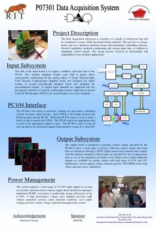
Project Description A continuation of last year’s project to design a user interface module to assist in the calibration of internal combustion engines This year’s goal is to design a PCB with supporting embedded software to achieve this goal • SauravJoshee (Team Leader, Hardware) • Dean Kooiman (I/O) • Josh Gabler (GUI)
The Existing Project • Last year’s group provided: • General embedded software (hardcoded functionality) • Semi-operable general purpose I/O • Box enclosure and hardware layout TCP/IP Internal combustion Engine Engine Control Unit
This Year’s Design Goals Hardware PCB layout System Block Diagram Boost Supply Finite Heat Element Analysis NetOS and ThreadX Improve I/O handlers Integrate Interrupt Service Routines Design Threads Dynamic GUI Design
PCB Layout System Block Diagram:
Range Input voltage3.2-3.4v Output Voltage 9v Output Current: .092A Boost Supply:
Finite Heat Element Analysis: Top layer Top layer(Simulation) Power Dissipation: Operating Conditions Cin= 0.00149 W Vin= 14V-22 V I out=2A Cout=7.456E-5 W D1= 0.7484 W L1= 0.2816 W U1= 0.7296 W Total power dissipated: 1.761W Power dissipation (Q) = Heat transfer coefficient (h) * Surface Area (SA) * (Maximum component temperature (T1) – Air temperature (T2))
General Purpose I/O Handlers • Fix Existing I/O Handlers • Interrupt Service Routines
Multi Threading with ThreadX • Design Considerations Allocate Stack Space Thread runs from stack pointer Thread can not grow out of stack space Hard to debug if stack to small
Dynamic GUI Design • Configuration Frame • Control Layout of the 7 generic frames • Dynamic I/O Assignment • Sensitivity, Range, Units • Generic Frame • Display Different variable configurations
Budget Salaries
Next Semester • Convert the GUI layouts into embedded LabView • Interrupt Service Routines need to be hooked into LabViews elemental I/O • Finish PCB design and Circuit Board • Query the engine controller over the network • Modify Variables on engine controller