Overview of CLEC Collocation Space and Architecture for Line Splitting Solutions
This document provides detailed insights into the proposed architecture for collocation space used by CLEC1 and CLEC2, including specifications for new line splitting for voice and data services. It covers connection points in the POT bay, including cross-connects and connecting blocks essential for delivering services to end users. Key components include configurations for shared splitter areas, network architecture under Docket No. UT-003013, and the implications for CLECs in terms of equipment setup and connectivity.

Overview of CLEC Collocation Space and Architecture for Line Splitting Solutions
E N D
Presentation Transcript
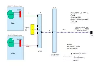
Network Network CLEC1 Collocation Space V H POT Bay V H Docket NO. UT-003013 Part B Exhibit RGS-2 Qwest Architecture with An ICDF 4 Data 2 Common Splitter Area New Line Splitting with CLEC2 Voice and CLEC 1 Data to the end user 1 EICT 6 3 CLEC2 Collocation Space NID POT Bay 6 cables 6 connecting blocks 4 cross connects 5 ICDF Voice = Connecting Block COSMIC/MDF = Cross Connect = Cables
Network Network CLEC1 Collocation Space V H POT Bay Docket NO. UT-003013 Part B Exhibit RGS-3 AT&T Proposed Architecture 4 Data 2 New Line Splitting with CLEC2 Voice and CLEC 1 Data to the end user Common Splitter Area EICT 1 3 NID CLEC2 Collocation Space POT Bay 5 cables 5 connecting blocks 3 cross connects 5 Voice = Connecting Block COSMIC/MDF = Cross Connect = Cables