Chapter 1 Introduction
Chapter 1 Introduction. Adapted from Computer Networking: A Top Down Approach, 6th edition, Jim Kurose, Keith Ross Addison-Wesley, March 2012. Chapter 1: introduction. Review : what ’ s the Internet? what ’ s a protocol? network edge; hosts, access net, physical media

Chapter 1 Introduction
E N D
Presentation Transcript
Chapter 1Introduction • Adapted from Computer Networking: A Top Down Approach, 6th edition, Jim Kurose, Keith RossAddison-Wesley, March 2012 Introduction
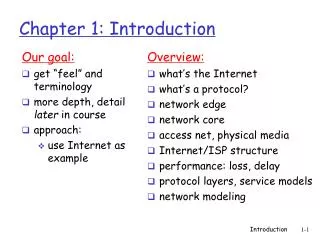
Chapter 1: introduction Review: what’s the Internet? what’s a protocol? network edge; hosts, access net, physical media network core: packet/circuit switching, Internet structure performance: loss, delay, throughput protocol layers, service models history Introduction
What’s the Internet: “nuts and bolts” view millions of connected computing devices: hosts = end systems running network apps PC server wireless laptop smartphone wireless links wired links router mobile network global ISP home network • communication links • fiber, copper, radio, satellite • transmission rate: bandwidth regional ISP • Packet switches: forward packets (chunks of data) • routers and switches institutional network Introduction
“Fun” internet appliances Web-enabled toaster + weather forecaster IP picture frame http://www.ceiva.com/ Tweet-a-watt: monitor energy use Slingbox: watch, control cable TV remotely Internet refrigerator Internet phones Introduction
Internet: “network of networks” Interconnected ISPs protocolscontrol sending, receiving of msgs e.g., TCP, IP, HTTP, Skype, 802.11 Internet standards RFC: Request for comments IETF: Internet Engineering Task Force What’s the Internet: “nuts and bolts” view mobile network global ISP home network regional ISP institutional network Introduction
What’s the Internet: a service view Infrastructure that provides services to applications: Web, VoIP, email, games, e-commerce, social nets, … provides programming interface to apps hooks that allow sending and receiving app programs to “connect” to Internet provides service options, analogous to postal service mobile network global ISP home network regional ISP institutional network Introduction
What’s a protocol? human protocols: “what’s the time?” “I have a question” introductions … specific msgs sent … specific actions taken when msgs received, or other events network protocols: machines rather than humans all communication activity in Internet governed by protocols protocols define format, order of msgs sent and received among network entities, and actions taken on msg transmission, receipt Introduction
a human protocol and a computer network protocol: Get http://www.awl.com/kurose-ross Got the time? 2:00 time What’s a protocol? Hi TCP connection request Hi TCP connection response <file> Q: other human protocols? Introduction
Chapter 1: roadmap 1.1 what is the Internet? 1.2 network edge end systems, access networks, links 1.3 network core packet switching, circuit switching, network structure 1.4 delay, loss, throughput in networks 1.5 protocol layers, service models 1.6 networks under attack: security 1.7 history Introduction
A closer look at network structure: network edge: hosts: clients and servers servers often in data centers mobile network global ISP home network • access networks, physical media: wired, wireless communication links regional ISP • network core: • interconnected routers • network of networks institutional network Introduction
Access networks and physical media Q: How to connect end systems to edge router? residential access nets institutional access networks (school, company) mobile access networks keep in mind: bandwidth (bits per second) of access network? shared or dedicated? Introduction
Access net: digital subscriber line (DSL) ISP voice, data transmitted at different frequencies over dedicated line to central office DSL access multiplexer central office telephone network DSL modem splitter DSLAM • use existing telephone line to central office DSLAM • data over DSL phone line goes to Internet • voice over DSL phone line goes to telephone net • < 2.5 Mbps upstream transmission rate (typically < 1 Mbps) • < 24 Mbps downstream transmission rate (typically < 10 Mbps) Introduction
C O N T R O L D A T A D A T A V I D E O V I D E O V I D E O V I D E O V I D E O V I D E O 5 6 7 8 9 1 2 3 4 Channels Access net: cable network cable headend … cable modem splitter frequency division multiplexing: different channels transmitted in different frequency bands Introduction
cable modem termination system data, TV transmitted at different frequencies over shared cable distribution network ISP Access net: cable network cable headend … cable modem splitter CMTS • HFC: hybrid fiber coax • asymmetric: up to 30Mbps downstream transmission rate, 2 Mbps upstream transmission rate • network of cable, fiber attaches homes to ISP router • homes share access networkto cable headend • unlike DSL, which has dedicated access to central office Introduction
often combined in single box cable or DSL modem router, firewall, NAT wireless access point (54 Mbps) wired Ethernet (100 Mbps) Access net: home network wireless devices to/from headend or central office Introduction
Enterprise access networks (Ethernet) institutional link to ISP (Internet) institutional router Ethernet switch institutional mail, web servers • typically used in companies, universities, etc • 10 Mbps, 100Mbps, 1Gbps, 10Gbps transmission rates • today, end systems typically connect into Ethernet switch Introduction
Wireless access networks shared wireless access network connects end system to router via base station aka “access point” wide-area wireless access • provided by telco (cellular) operator, 10’s km • between 1 and 10 Mbps • 3G, 4G: LTE wireless LANs: • within building (100 ft) • 802.11b/g (WiFi): 11, 54 Mbps transmission rate to Internet to Internet Introduction
Host: sends packets of data two packets, L bits each 1 2 R: link transmission rate host L (bits) R (bits/sec) time needed to transmit L-bit packet into link packet transmission delay = = host sending function: • takes application message • breaks into smaller chunks, known as packets, of length L bits • transmits packet into access network at transmission rate R • link transmission rate, aka link capacity, aka link bandwidth
Physical media bit:propagates betweentransmitter/receiver pairs physical link: what lies between transmitter & receiver guided media: signals propagate in solid media: copper, fiber, coax unguided media: signals propagate freely, e.g., radio twisted pair (TP) two insulated copper wires Category 5: 100 Mbps, 1 Gpbs Ethernet Category 6: 10Gbps Introduction
Physical media: coax, fiber coaxial cable: two concentric copper conductors bidirectional broadband: multiple channels on cable HFC fiber optic cable: • glass fiber carrying light pulses, each pulse a bit • high-speed operation: • high-speed point-to-point transmission (e.g., 10’s-100’s Gpbs transmission rate) • low error rate: • repeaters spaced far apart • immune to electromagnetic noise Introduction
Physical media: radio signal carried in electromagnetic spectrum no physical “wire” bidirectional propagation environment effects: reflection obstruction by objects interference radio link types: • terrestrial microwave • e.g. up to 45 Mbps channels • LAN (e.g., WiFi) • 11Mbps, 54 Mbps • wide-area (e.g., cellular) • 3G cellular: ~ few Mbps • satellite • Kbps to 45Mbps channel (or multiple smaller channels) • 270 msec end-end delay • geosynchronous versus low altitude Introduction
1.1 what is the Internet? 1.2 network edge end systems, access networks, links 1.3 network core packet switching, circuit switching, network structure 1.4 delay, loss, throughput in networks 1.5 protocol layers, service models 1.6 networks under attack: security 1.7 history Chapter 1: roadmap Introduction
mesh of interconnected routers packet-switching: hosts break application-layer messages into packets forward packetsfrom one router to the next, across links on path from source to destination each packet transmitted at full link capacity The network core Introduction
Packet-switching: store-and-forward takes L/R seconds to transmit (push out) L-bit packet into link at R bps store and forward:entire packet must arrive at router before it can be transmitted on next link one-hop numerical example: L = 7.5 Mbits R = 1.5 Mbps one-hop transmission delay = 5 sec L bits per packet 1 3 2 source destination R bps R bps • end-end delay = 2L/R (assuming zero propagation delay) more on delay shortly … Introduction
Packet Switching: queueing delay, loss C R = 100 Mb/s A D R = 1.5 Mb/s B E queue of packets waiting for output link queuing and loss: • If arrival rate (in bits) to link exceeds transmission rate of link for a period of time: • packets will queue, wait to be transmitted on link • packets can be dropped (lost) if memory (buffer) fills up Introduction
Two key network-core functions routing:determines source-destination route taken by packets • routing algorithms forwarding:move packets from router’s input to appropriate router output routing algorithm local forwarding table header value output link 0100 0101 0111 1001 3 2 2 1 1 0111 2 3 dest address in arriving packet’s header Network Layer
Alternative core: circuit switching end-end resources allocated to, reserved for “call” between source & dest: In diagram, each link has four circuits. call gets 2nd circuit in top link and 1st circuit in right link. dedicated resources: no sharing circuit-like (guaranteed) performance circuit segment idle if not used by call (no sharing) Commonly used in traditional telephone networks Introduction
Circuit switching: FDM versus TDM Example: 4 users FDM frequency time TDM frequency time Introduction
Packet switching versus circuit switching example: 1 Mb/s link each user: 100 kb/s when “active” active 10% of time circuit-switching: 10 users packet switching: with 35 users, probability > 10 active at same time is less than .0004 * packet switching allows more users to use network! Q: how did we get value 0.0004? Q: what happens if > 35 users ? N users ….. 1 Mbps link * Check out the online interactive exercises for more examples Introduction
great for bursty data resource sharing simpler, no call setup excessive congestion possible: packet delay and loss protocols needed for reliable data transfer, congestion control Q: How to provide circuit-like behavior? bandwidth guarantees needed for audio/video apps still an unsolved problem (chapter 7) is packet switching a “slam dunk winner?” Packet switching versus circuit switching Q: human analogies of reserved resources (circuit switching) versus on-demand allocation (packet-switching)? Introduction
Internet structure: network of networks • End systems connect to Internet via access ISPs (Internet Service Providers) • Residential, company and university ISPs • Access ISPs in turn must be interconnected. • So that any two hosts can send packets to each other • Resulting network of networks is very complex • Evolution was driven by economics and national policies • Let’s take a stepwise approach to describe current Internet structure
Internet structure: network of networks Question: given millions of access ISPs, how to connect them together? … … … … access net access net access net access net access net access net access net access net access net access net access net access net access net access net access net access net … …
Internet structure: network of networks Option: connect each access ISP to every other access ISP? … … … … connecting each access ISP to each other directly doesn’t scale: O(N2) connections. … … … … access net access net access net access net access net access net access net access net access net access net access net access net access net access net access net access net … … …
Internet structure: network of networks Option: connect each access ISP to a global transit ISP? Customer and provider ISPs have economic agreement. … … … … globalISP access net access net access net access net access net access net access net access net access net access net access net access net access net access net access net access net … …
Internet structure: network of networks But if one global ISP is viable business, there will be competitors …. … … ISP B ISP A ISP C … … access net access net access net access net access net access net access net access net access net access net access net access net access net access net access net access net … …
Internet structure: network of networks But if one global ISP is viable business, there will be competitors …. which must be interconnected Internet exchange point … … ISP B ISP C ISP A IXP IXP … … access net access net access net access net access net access net access net access net access net access net access net access net access net access net access net access net peering link … …
Internet structure: network of networks … and regional networks may arise to connect access nets to ISPS … … ISP B ISP C ISP A IXP IXP … … access net access net access net access net access net access net access net access net access net access net access net access net access net access net access net access net regional net … …
Internet structure: network of networks … and content provider networks (e.g., Google, Microsoft, Akamai ) may run their own network, to bring services, content close to end users … … ISP B ISP B ISP A IXP IXP … … Content provider network access net access net access net access net access net access net access net access net access net access net access net access net access net access net access net access net regional net … …
Internet structure: network of networks at center: small # of well-connected large networks “tier-1” commercial ISPs(e.g., Level 3, Sprint, AT&T, NTT), national & international coverage content provider network (e.g, Google): private network that connects it data centers to Internet, often bypassing tier-1, regional ISPs Tier 1 ISP Tier 1 ISP Google IXP IXP IXP Regional ISP Regional ISP access ISP access ISP access ISP access ISP access ISP access ISP access ISP access ISP Introduction
Tier-1 ISP: e.g., Sprint POP: point-of-presence to/from backbone peering … … … … … to/from customers Introduction
Chapter 1: roadmap 1.1 what is the Internet? 1.2 network edge end systems, access networks, links 1.3 network core packet switching, circuit switching, network structure 1.4 delay, loss, throughput in networks 1.5 protocol layers, service models 1.6 networks under attack: security 1.7 history Introduction
How do loss and delay occur? packets queue in router buffers packet arrival rate to link (temporarily) exceeds output link capacity packets queue, wait for turn packet being transmitted (delay) packets queueing(delay) free (available) buffers: arriving packets dropped (loss) if no free buffers A B Introduction
Four sources of packet delay dproc: nodal processing check bit errors determine output link typically < msec transmission A propagation B nodal processing queueing dnodal = dproc + dqueue + dtrans + dprop dqueue: queueing delay • time waiting at output link for transmission • depends on congestion level of router Introduction
dtrans and dprop very different Four sources of packet delay transmission A propagation B nodal processing queueing dnodal = dproc + dqueue + dtrans + dprop dprop: propagation delay: • d: length of physical link • s: propagation speed in medium (~2x10⁸ m/sec) • dprop = d/s dtrans: transmission delay: • L: packet length (bits) • R: link bandwidth (bps) • dtrans= L/R * Check out the Java applet for an interactive animation on trans vs. prop delay Introduction
Caravan analogy cars “propagate” at 100 km/hr toll booth takes 12 sec to service car (bit transmission time) car~bit; caravan ~ packet Q: How long until caravan is lined up before 2nd toll booth? time to “push” entire caravan through toll booth onto highway = 12*10 = 120 sec time for last car to propagate from 1st to 2nd toll both: 100km/(100km/hr)= 1 hr A: 62 minutes 100 km 100 km ten-car caravan toll booth toll booth Introduction
Caravan analogy (more) suppose cars now “propagate” at 1000 km/hr and suppose toll booth now takes one min to service a car Q: Will cars arrive to 2nd booth before all cars serviced at first booth? A: Yes! after 7 min, 1st car arrives at second booth; three cars still at 1st booth. 100 km 100 km ten-car caravan toll booth toll booth Introduction
R: link bandwidth (bps) L: packet length (bits) a: average packet arrival rate Queueing delay (revisited) average queueing delay traffic intensity = La/R • La/R ~ 0: avg. queueing delay small • La/R -> 1: avg. queueing delay large • La/R > 1: more “work” arriving than can be serviced, average delay infinite! La/R ~ 0 La/R -> 1 * Check out the Java applet for an interactive animation on queuing and loss Introduction
“Real” Internet delays and routes what do “real” Internet delay & loss look like? traceroute program: provides delay measurement from source to router along end-end Internet path towards destination. For all i: sends three packets that will reach router i on path towards destination router i will return packets to sender sender times interval between transmission and reply. 3 probes 3 probes 3 probes Introduction
“Real” Internet delays, routes traceroute: gaia.cs.umass.edu to www.eurecom.fr 3 delay measurements from gaia.cs.umass.edu to cs-gw.cs.umass.edu 1 cs-gw (128.119.240.254) 1 ms 1 ms 2 ms 2 border1-rt-fa5-1-0.gw.umass.edu (128.119.3.145) 1 ms 1 ms 2 ms 3 cht-vbns.gw.umass.edu (128.119.3.130) 6 ms 5 ms 5 ms 4 jn1-at1-0-0-19.wor.vbns.net (204.147.132.129) 16 ms 11 ms 13 ms 5 jn1-so7-0-0-0.wae.vbns.net (204.147.136.136) 21 ms 18 ms 18 ms 6 abilene-vbns.abilene.ucaid.edu (198.32.11.9) 22 ms 18 ms 22 ms 7 nycm-wash.abilene.ucaid.edu (198.32.8.46) 22 ms 22 ms 22 ms 8 62.40.103.253 (62.40.103.253) 104 ms 109 ms 106 ms 9 de2-1.de1.de.geant.net (62.40.96.129) 109 ms 102 ms 104 ms 10 de.fr1.fr.geant.net (62.40.96.50) 113 ms 121 ms 114 ms 11 renater-gw.fr1.fr.geant.net (62.40.103.54) 112 ms 114 ms 112 ms 12 nio-n2.cssi.renater.fr (193.51.206.13) 111 ms 114 ms 116 ms 13 nice.cssi.renater.fr (195.220.98.102) 123 ms 125 ms 124 ms 14 r3t2-nice.cssi.renater.fr (195.220.98.110) 126 ms 126 ms 124 ms 15 eurecom-valbonne.r3t2.ft.net (193.48.50.54) 135 ms 128 ms 133 ms 16 194.214.211.25 (194.214.211.25) 126 ms 128 ms 126 ms 17 * * * 18 * * * 19 fantasia.eurecom.fr (193.55.113.142) 132 ms 128 ms 136ms trans-oceanic link * means no response (probe lost, router not replying) * Do some traceroutes from exotic countries at www.traceroute.org Introduction
Packet loss queue (aka buffer) preceding link in buffer has finite capacity packet arriving to full queue dropped (aka lost) lost packet may be retransmitted by previous node, by source end system, or not at all buffer (waiting area) packet being transmitted A B packet arriving to full buffer is lost * Check out the Java applet for an interactive animation on queuing and loss Introduction