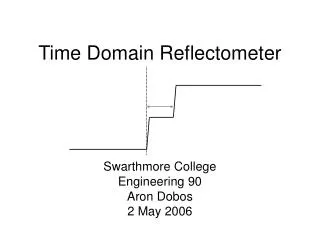
Time Domain Reflectometer
Time Domain Reflectometer. TECHTRONIX. Time Domain Reflectometer. INTRODUCTION Transmission Line Discontinuities VOP, Velocity of Propagation How a TDR Works Signatures Blind Spots Why use different PULSE WIDTHS Different types of TDRs Demo Program ( wv142.exe ).

Time Domain Reflectometer
E N D
Presentation Transcript
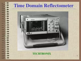
Time Domain Reflectometer TECHTRONIX
Time Domain Reflectometer INTRODUCTION • Transmission Line Discontinuities • VOP, Velocity of Propagation • How a TDR Works • Signatures • Blind Spots • Why use different PULSE WIDTHS • Different types of TDRs • Demo Program ( wv142.exe ) TDRs can locate and identify faults in metallic paired cabling. (UTP, STP, & Coax) OTDR can locate and identify faults in Optical cabling. TDRs can locate major or minor cabling problems including; sheath faults, broken conductors, water damage, loose connectors, crimps, cuts, smashed cables, shorted conductors, system components, and a variety of other fault conditions. By Steve Gallant, cne
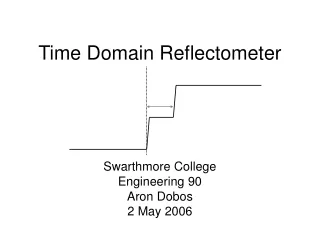
Transmission Line Discontinuities Idealized Transmission Line
How TDRs Work • The TDR operates similar to radar in principle. A pulse is transmitted down a cable from the TDR. When that pulse reaches a discontinuity like the end of the cable or a fault along the cable, part or all of the pulse is reflected back to the TDR. • The TDR measures the time it takes for the signal to travel down the cable and then get reflected back. The TDR then converts this time to distance and displays that information. • Install wv142.exe program in windows and see the TDR simulations 1000 nsec = 1 micro sec. 1 mil = 0.001 1 micro = 0.000,001 1 nano = 0.000,000,001
SIGNATURES Reflection
Blind Spots • The initial pulse that the TDR generates has a width to it. During the time the initial pulse is active a reflected pulse will not be seen. This distance is known as the blind spot. The length of the blind spot varies with the pulse width. The larger the pulse width, the larger the blind spot. • If there is a fault within the first few feet of cable, it will be hidden in the blind spot. By adding a few feet to the front of the cable the blind spot can be tested. When adding a length of cable to eliminate the blind spot, remember the TDR is also reading the length of this jumper cable. The length of the jumper must be subtracted from the cable when measuring from the point of connection.
Why different PULSE WIDTHS Time Domain Reflectometers may include these Widths : 2 nsec 10 nsec 100 nsec 1000 nsec 2000 nsec 4000 nsec
Different Types of TDRs The traditional method is to display the actual waveform or "signature" of the cable. It uses a CRT or an LCD. It will display the transmitted pulse generated by the TDR and any reflections which are caused by impedance discontinuities. Another method is a numeric readout which supplies the distance indication in feet/meters to the first major reflection caused by any discontinuity. Some instruments also display if the fault is an OPEN or SHORT indicating a HIGH IMPEDANCE change or a LOW IMPEDANCE change respectively. Traditional Waveform supply more information than do the digital numeric versions. However, the simplified digital models are less expensive and easier to operate. By Steve Gallant, cne