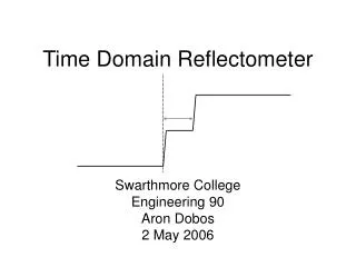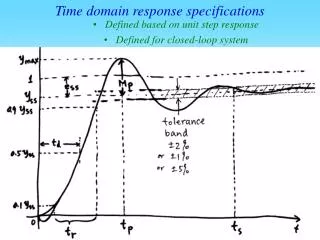
Time Domain Circuits
Time Domain Circuits. R. V in. V out. C. GND. GND. Passive Filters. Equate currents:. C(dVout/dt) = (V in – V out ) / R. t = R * C. t (dV out /dt) = (Vin – Vout). C. V in. V out. C ( d(Vin – Vout)/dt) = Vout/R. R. t (d(Vin – Vout)/dt) = Vout. Response of a linear system.

Time Domain Circuits
E N D
Presentation Transcript
R Vin Vout C GND GND Passive Filters Equate currents: C(dVout/dt) = (Vin – Vout) / R t = R * C t(dVout/dt) = (Vin – Vout) C Vin Vout C ( d(Vin – Vout)/dt) = Vout/R R t(d(Vin – Vout)/dt) = Vout
Response of a linear system Impulse response of a low-pass filter V=(1)exp( -t/t ) V = V(0)exp( -t / t ) V = (e-1)exp( -t/t ) V = (e-2)exp( -t/t ) • Behavior is independent of boundary conditions • Boundary conditions only scale the result • (double the input, double the output)
A Unity-Gain Follower Amp Gain = Av Av Solving: Vout = Vin 1 + Av
A Unity-Gain Follower Amp Gain = Av Solving: Vout~ Vin
A Unity-Gain Follower Amp Gain = Av Solving: Vout ~ Vin
A Low-Pass Filter Ibias(k) (Vin - Vout) /(2 UT) C (dVout/dt) = Ibias tanh(k(Vin - Vout)/(2 UT) )
t (dVout/dt) + Vout = Vin t = C UT / k Ibias Time-constant changes with bias A Low-Pass Filter Ibias(k) (Vin - Vout) /(2 UT) C (dVout/dt) =
A Low-Pass Filter C (dVout/dt) = Ibias tanh(k(Vin - Vout)/(2 UT) ) This is not linear…. “Small-signal analysis: How small is “small”? |Vin - Vout| < 2UT
I Vout Vin C1 dVout(t) dt dVout(t) dt GND Follower Integrator(Simplest Gm-C Filter) If an ideal op-amp, then Vin = Vout By KCL: Gm(Vin - Vout ) = C1 Defining t = C1 / Gm UT / k Ibias Vin = Vout + t We can set Gm and build C sufficiently big enough (slow down the amplifier), or set by C (smallest size to get enough SNR), and change Gm.
A Low-Pass Filter C (dVout/dt) = Ibias tanh(k(Vin - Vout)/(2 UT) ) This is not linear…. tanh(X) = +/- 1 “Small-signal analysis: How small is “small”? |Vin - Vout| < 2UT |Vin - Vout| > 10UT
A Low-Pass Filter Ibias tanh(k(Vin - Vout)/(2 UT) ) C (dVout/dt) = Ibias (dVout/dt) = 1 / t Slew Rate = C / Ibias Slew-Rate changes with bias
Tuning Frequency using Bias Current C = 1pF, W/L of input transistors = 30, Ith ~ 10mA. This approach is the most power-efficient approach for any filter. All electronically tunable: Advantage: we can electronically change the corner Disadvantage: we need a method to set this frequency (tuning)
R Vin Vout C GND Comparing Low-Pass Filters • Transistor Capacitor design • Time-constant is • electrically tunable • No input current load • Linear Filtering • Requires no additional • power