Download
1 / 13
130 likes | 303 Vues
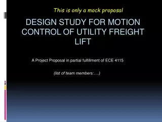
This is only a mock proposal. A Project Proposal in partial fulfillment of ECE 4115. (list of team members:….). design study for Motion control of utility freight lift. Outline. Introduction Problem description Automatic control approach Work plan Anticipated challenges and results

E N D
This is only a mock proposal A Project Proposal in partial fulfillment of ECE 4115 (list of team members:….) design study for Motion control of utility freight lift
Outline • Introduction • Problem description • Automatic control approach • Work plan • Anticipated challenges and results • Summary & conclusion
Introduction Of the worldwide market ~$60 B (2012) for elevators including industrial products, utility freight lifts occupy a niche market of ~ 12%. However, these products have a high growth rates all over the world in both developed and emerging regional economies. They are expected to gain a larger share in the projected market of $90 billion of elevators in 2015. Small and fast freight lifts enjoy high demand thanks to the trend of increasing robotics/automation in manufacturing and warehousing distribution for online commerce, and also to a worldwide increase in construction activities as the global economy recovers. These automatic lifts move goods and equipment up and down large-scale facilities and construction sites like a vertical conveyor, except that they carry larger payload and are intended for random access. They are required to have high throughput by moving substantially faster than the typical <1 m/s freight lifts common for other industrial applications. Also, automation applications without the supervision of human operators demand these lifts to be more accurate and interface well with other warehousing and manufacturing robots and automated equipment. This project is a study of automatic control approach for a freight lift for both speed and accuracy. The objective is a design that can be implemented with a prototype to be tested by a potential customer. The scope of this project is only about the motion control of the lift and not other mechanical or electro-mechanical aspects such as structural railing strength, vibration, shock, and thermal properties. In addition, the study assumes other components of the systems such as brakes, dampers, and other actuators are available to assist the control system. The challenge of this problem is an automatic control system that is robust and reliable. Not intended for human use, such a lift has no ergonomic constraints and is expected to operate at its kinetic capability limit, yet low cost and efficient.
Problem discussion The customer requires the lift to carry payload up to 1000 kg for a height up to 100 m with the fastest possible throughput rate, and is concerned of energy efficiency. A study of kinetic performance led to the choice of a conveyor-like system with a maximum speed of 8 m/s as the most suitable for the customer’s requirement. The lift has a drag resistance: F=- bv where v is the lift velocity and drag coefficient b~200-300 N s/m. The problem is to design an approach to control the force on the lift, and to recommend performance specification for the lift driver engine, which remains to be determined. The system has static restraints including brakes, dampers and latches to lock the lift in place while not in motion. The static restraint system requires the lift have positioning accuracy better than 5 cm. The functioning diagram of the control system is shown in the next figure.
Input: • Destination position (height) • Position sensor data • Lift cable strain sensor data • Payload and lift net weight data from combined sensors • Speed and acceleration sensor data • Vibration sensor data • Side wind force data if used outdoor • Video signals from monitor cameras mounted along the rail and in the lift • Output: • Signal to drive the engine of the lift • Report of performance and system data to the higher level system control and data logging • Detection and alert for anomaly Control system • Design criteria • Basic performance of speed and accuracy: meets the customer’s desire of high throughput and concern of energy usage by achieving the best possible allowed by theoretical limit, and stays within other constraints to maintain the system mechanical integrity and for its long-life. • Robustness and resiliency: the control design should have high tolerance for large variation of various control parameters and in the presence of expected disturbances of the operation environment. It must have self-corrected mechanism to tolerate sensor data inaccuracy or errors.
Technical approach The study will perform an estimation of the theoretical boundary of possible performance of the system as an initial guideline. In this initial phase, the study is restricted to consider common closed-loop control designs, including proportional controller, PID controller, rate control and hybrid approaches. Modeling will be done for the various approaches and computer simulation will be performed. Each design will be evaluated for advantageous and disadvantageous features, so that a hybrid approach may be designed to co-opt the most suitable features of each approach. The block diagrams for the designs to be studied are shown below. Place holders for various figures
Example only… In the proportional controller approach, we will consider first that there is a weight sensor and the engine will supply a force to levitate the lift, which is different from the force that will drive the lift from the signal that is provided from the controller… weight sensor + To lift driver engine + controller Etc.
Tasks and schedule Time line Task Calculating the theoretical system performance boundary Building models for classical closed-loop control approaches: P, PID, rate controller, hybrid. • Computer simulation and comparison of various closed loop control designs: • Performance with disturbances (steady and transient force) • Force and response speed requirement of driver engine Analysis and best approach recommendation Final result milestone report
Anticipated challenges & results • It is likely the most difficult aspect is to find a stable design that can handle various disturbances. The main disturbances can be of two types: • Continuous external force that can be varying. In such a case, the lift must still stay reasonably close to speed limit and arrive destination with accuracy. • Impact force that results in a momentum (speed) change that is difficult to adjust especially when the lift is near the destination. • In addition, disturbance can be a sudden mass change such as some heavy object hooked onto the lift, or is dropped from the lift. The change may occur while in motion and the lift must remain steady and reach its destination • In addition, the design must also accept a wide latitude of control parameters such as gain (e. g. proportional, integral, derivative) without falling out of required performance boundary.
Preliminary results Example only… Simulation results for a proportional controller
Preliminary results Example only… Simulation results for a proportional controller
Summary and conclusion This project is to design an automatic controller for a small-capacity high-speed industrial freight lift for customer application. The key restraint is the lift speed and the requirement is to achieve accurate positioning for completely automated operation without human supervision. The proposed approach is to evaluate various classical closed loop designs including PID and rate controller. The work involves computer simulation, analysis, comparison of various designs, and to propose a final design.