Download
1 / 32
360 likes | 668 Vues
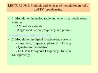
LECTURE 5-6. receivers OF RADIO and TV broadcastING systems. GENERAL INFORMATION ABOUT RECEIVERS OF RADIO AND TV BROADCASTING SYSTEMS MAIN TYPES OF BROADCASTING RECEIVERS RECEIVER NOISE FACTOR AND SENSITIVITY (SENSEPTIBLITY) MAIN ELEMENTS OF RECEIVERS SOFTWARE DEFINED RADIO (SDR).

E N D
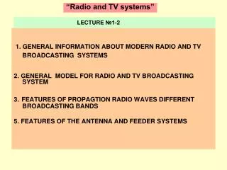
LECTURE 5-6. receivers OF RADIOand TV broadcastING systems • GENERAL INFORMATION ABOUT RECEIVERS OF RADIO AND TV BROADCASTING SYSTEMS • MAIN TYPES OF BROADCASTING RECEIVERS • RECEIVER NOISE FACTOR AND SENSITIVITY (SENSEPTIBLITY) • MAIN ELEMENTS OF RECEIVERS • SOFTWARE DEFINED RADIO (SDR)
1. GENERAL INFORMATION ABOUT RECEIVERS OF RADIO AND TV BROADCASTING SYSTEMS RS RS+interference Оконечное устройство Soundand(or)image transducer TX RX Interference The general block diagram of radio channel of thebroadcast and TV systems A sound or image, is transformed in voltage or current, modulates a high-frequency carrier. As a result the output radio signal (RS) of TX can be amplitude, phase or frequency modulated • Interference. At propagation radio signal in free space and feed lines it take place distortions, which are conditioned: • by irregularity of propagation medium; • by the artificial and natural restriction ; • byinternalnoisesofantennaandreceiveranditsimperfection • Radio receiver(RX) intended for transformation input signals with the purpose of extraction of useful information. • RX must contain units, necessary for realization of the followings operations: • selection from all of aggregate of electric vibrations, pointed in aerial the external electromagnetic fields, signal from a necessary radio transmitter; • amplfication of high-frequency signals; • demodulation signals; • strengthening of prorectifying signal.
The radioreceivers is designed to extraction of useful signals received from the receiving antenna, its amplification and conversion to the form required for the normal operation of terminals (loudspeaker, monitor, etc.) By apointment: radio broadcasting, TV broadcasting, wireless communication, navigation, radiolocation, radio control, etc. By type of signal:analog or digital By the method of signal processing: - with filter processing;- with correlation-filter processing. By frequency band:LF, MF, SF, VHF, UHF, SHF, et cetera The main functions of radio receivers: the selectivity (separation of the useful signal); amplification (to the level required for normal working terminal); conversion (to increase selectivity and stable amplification); automatic gain control (for widening dynamic rang) ; demodulation (selection of modulation law) or measure the signal parameters.
Sensitivity - the minimum power or voltage at the input RX, which provide a given quality of signal processing Peak (noise-limited) sensitivity - the minimum power Psmin or voltage Uc minat the receiver input at which the SNR at the output of the linear part RX equal to one (Ps / Pn = 1 or Uc / Un = 1); Real (actual or threshold) sensitivity - minimum power or voltage at the receiver input at which the predetermined reception quality (given the SNR at the output of the linear part RX). At wavelength > 1 m, when the resonans circuits RX can be considered as systems with lumped parameters, the sensitivity is taken in units of voltage - microvolts or millivoltsUc min. If <1 m - in terms of power Pc min. Real sensitivity radio receiver is in the range of 50 ... 300 μV, depending on the quality class. Sensitivity of satellite TV receiver can be up 10-14 ... 10-15 W. For broadcast receivers with ferrite antenna uses the concept of sensitivity in field strength. It has a value from 0.3 to 5 mV/m.
U c f p УВЧ УНЧ СМ U гр f p f = f г р Гетеродин Block diagram of the receiver of direct amplification . The block diagram of a superheterodyne receiver 2. MAIN TYPES OF BROADCASTING RECEIVERS Frequency Converter Block diagram of direct conversion receivers SDR RX
Parameters of the radio receivers Frequency range - the entire band of frequencies, which can receive signals Dynamic range RX describes its ability to receive signals without distortion Pвых D,дБ=10 lg(Pinmax/Pinmin) Selectivity: by the frequency (on the next channel, the image channel) by the waveform, by the polarization у
Quantitative estimation of noises Thermal (heat) noise Stored energy Nyquist formula Shot noise Power rating (nominal power) Shottky formula – noise power at matched load
3. RECEIVER NOISE FACTOR (figure, ratio) INPUT. UNIT LNA MIX IFA Detector G IfКрIN ≈1
RECEIVERS SENCITIVITY Noise power output Power output noise, converted to the input Rs=RaRL=Rin → Nyquist formula k=1,38·10-23W/Hz grad
4. MAIN ELEMENTS OF RECEIVERS Low-nose amplifier Balanced frequency converter
С >> С bl F D U U LFout intm R R F L С F HF Demodulators (detectors) — AM — FM — PM Amplitude detectors LF
Demodulation of ASK signal а б в Demodulation of PM signal
Phase detector Ud1= U0 + Us /2; Ud2= U0 - Us /2. m << 1 Us/U0 = m m = 1 Synchronous detector Output voltage phase detector for in-phase input and reference signals φ =0 is proportional to the input signal Us, and the phase detector is converted in the synchronous detector. These detectors, due to their high linearity, are widely used in analog TV for demodulation of the image signals and in digital TV for demodulating PSK signals.
compression expansion
BHF BIF AGC BD BLF (BDP) LNA MIX PreIFA Matched filter –Main IFA АD LFA f IF= |f1 – fs | _ X Main IFA PD ADC DSP f2 PD ADC f1 o DAC FS 90 Block diagram of the analog – digital receiver
ADC have not affected on RX noise factor If only For ADC 1107ПВ2 L=8 L FT , MHz D, dB For ADC AD9260 L=16
The twentieth century saw the explosion of hardware defined radio (HDR) as a means of communicating all forms of audible; visual, and machine-generated information over vast distances. Most radios are hardware defined with little or no software control; they are fixed in function for mostly consumer items for broadcast reception. They have a short life and are designed to be discarded and replaced. Software defined radio (SDR) uses programmable digital devices to perform the signal processing necessary to transmit and receive baseband information at radio frequency. Devices such as digital signal processors (DSPs) and field programmable gate arrays (FPGAs) use software to provide them with the required signal processing functionality. This technology offers greater flexibility and potentially longer product life, since the radio can be upgraded very cost effectively with software.
Software Defined Radio (SDR) SDRequipment - these are elements of the wireless network which operating modes and parameters can be changed or expanded after the elements are made using the software.
Modulated signal can to present by sum of two quadrature component
Zero IF Quadrature Product Detector One cycle Sine Wave at Sampled Frequency Fo