Download
1 / 26
260 likes | 478 Vues
Electronic Restoration of Radio Receivers. Original presentation to NJARC 12 Aug 94 Al Klase. INTRODUCTION. What is the most magical thing about a radio receiver?. REPAIR vs. RESTORATION. Repair: Location and resolution of a few localized faults. We might repair a 10 year old radio.

E N D
Electronic Restoration of Radio Receivers Original presentation to NJARC 12 Aug 94 Al Klase Radio Restoration
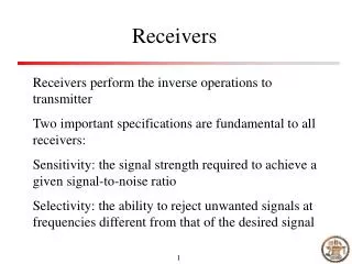
INTRODUCTION • What is the most magical thing about a radio receiver? Radio Restoration
REPAIR vs. RESTORATION • Repair: Location and resolution of a few localized faults. We might repair a 10 year old radio. • Restoration: Sweeping obviation of global problems. 60 year old set are candidates for restoration. Radio Restoration
GOLDEN ERA PROBLEMS • Greatly increased component count • Early state of the art: Poor long term reliability. • Resulting in: • Dead electrolytic caps • Leaky paper caps • Changed resistor values • Decay Radio Restoration
PHILOSOPHY • Let's make it work like it did when it was new. • Let's make the set stay fixed on into the next century. • Some sets may be too significant to touch. Radio Restoration
PHILOSOPHY (2) • "Shotgun" replacement of any suspect components. • Substitute with modern parts. • Preservation of craftsmanship. • Modern components hidden below-deck are acceptable. Radio Restoration
VISUAL INSPECTION • Before you buy: • Gross damage • Missing parts • Major modifications • Irreparable cosmetic problems Radio Restoration
VISUAL INSPECTION (2) • After it's too late: • Burned components • Leaking capacitors • Beware the broken band switch! Radio Restoration
POWER TRANSFORMER • This is probably the most expensive component. • Don't just plug 'er in and turn 'er on. A shorted component could burn out the transformer. • But, check the transformer before expending a lot of effort on the set. Radio Restoration
TRANSFORMER TEST • Remove rectifier tube. • Turn set on. • Tubes and pilot lights should light. • Check HV and filament voltages at rectifier socket. Radio Restoration
TYPICAL POWER SUPPLY Radio Restoration
INSTALL A FUSE • Install clip-type fuse holder, under the chassis, in the power transformer primary circuit. • Use a reasonable value fuse. • The rated power consumption, times 120%, divided by the line voltage, equals the necessary fuse value. • This is probably in the neighborhood of 1 amp. Radio Restoration
CLEANING • Clean as you go. • Scribe tube numbers on the bases. • Does everyone know about GOJO? • Don't use water based cleaners on bakelite. • Be really careful with dials etc. Radio Restoration
LUBRICATION • Lithium grease on capacitor bearings. • Light oil on shafts etc. • TV tuner cleaner on switch contact, volume controls, and tuning-cap shaft ground connections. Radio Restoration
ELECTROLYTICS • Replace them all! • Power supply filters • Cathode bypasses • Leave exposed cans in place • Disconnect • Install terminal strips to hold new caps below deck. They'll generally be much smaller than the originals. • Don't use drastically over-value replacements, particularly for the PS input filter. Higher than normal system voltage could occur. Radio Restoration
PAPER CAPS • Paper caps are all suspect! • Wax coated units are almost surely leaky. • Replace with ceramic or plastic caps. • Mica caps are generally OK. • Try not to mess with frequency determining components. Radio Restoration
Replace just one component at a time! Radio Restoration
CAPS IN RF AND IF AMPS Radio Restoration
CAPS IN RESISTANCE COUPLED STAGES Radio Restoration
THE OLD "DON'T BE VAGUE ASK FOR SPRAGUE " TRICK • When replacing components, avoid digging into the solder joint on terminal strips and tube sockets. • The Sprague capacitor people used to ship "QUIG" connectors with their replacement caps. • These are small solder-coated coils of wire used to sleeve the new cap leads to the cut-off leads of the old component. Radio Restoration
SPRAGUE (continued) • Use the shank of a small drill bit held in a pin vise to form a coil on the new part. • Slip these over the old leads and solder. • This preserves the craftsmanship of the original wiring job. • Not only that, its quick! Radio Restoration
Pig-tail Tool Radio Restoration
Replacement Radio Restoration
RESISTORS • Watch for resistors that have changed in value. • Resistance usually increases. • High values, greater than 100K, are more effected. • This is not as universal a problem as the leaky cap syndrome. • Spot check a few units in each set. • Remember these are usually + 20% units. Look for drastic changes. Radio Restoration
OTHER DETAILS • Test the tubes. • Replace suspect line cords. • Restring the dial cord if frayed. Radio Restoration
CONCLUSION • If you follow this procedure, the set will usually "come up" easily with minimal trouble shooting and repair. • Resist the urge to align a poorly performing set until after it’s restored. As an old race car mechanic told me: “Don’t even try to tune junk!" Radio Restoration