Download
1 / 25
250 likes | 430 Vues
6. Receivers. Receiver Characteristics: Sensitivity and Selectivity. Sensitivity Minimum input signal (voltage) required to produce specified output. Noise floor Input noise. Selectivity Extent to which receiver capable of differentiating between desired signal and other frequencies.

E N D
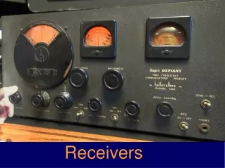
6 Receivers
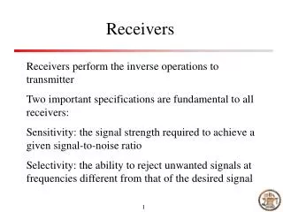
Receiver Characteristics: Sensitivity and Selectivity • Sensitivity • Minimum input signal (voltage) required to produce specified output. • Noise floor • Input noise. • Selectivity • Extent to which receiver capable of differentiating between desired signal and other frequencies.
The Tuned Radio-Frequency Receiver • Tuned Radio Frequency (TRF) Receivers • Three stages of RF amplification; each stage preceded by separate variable-tuned circuit. • Adjusted by individual variable capacitors. • Variable selectivity over its intended tuning range.
Superheterodyne Receivers • Frequency Conversion • Mixer (first detector) performs frequency conversion process. • Tuned-Circuit Adjustment • Key to superheterodyne operation • To make LO frequency track with circuit or circuits that are tuning incoming radio signal so difference is constant frequency (the IF).
Superheterodyne Receivers • Image Frequency • Undesired received signal. • Most of gain in superheterodyne receiver occurs in IF amplifiers at fixed frequency. • Double conversion • Solve image frequency problems. • RF amplifier with its own input tuned circuit helps to minimize problem.
Superheterodyne Receivers • Double Conversion • Stepping down RF signal to a first, high IF frequency and then mixing down again to second, lower, final IF frequency. • Image frequencies not major problem for low-frequency carriers.
Superheterodyne Receivers • Up-Conversion • IF at higher frequency than received signal. • Preselector • Responsible for image frequency rejection characteristics of receiver.
Superheterodyne Receivers • A Complete AM Receiver • Auxiliary AGC diode • Additional gain control for strong signals; enhances range of signals that can be compensated for by receiver.
Superheterodyne Receivers • SSB Receivers • Additional mixer and beat-frequency oscillator (BFO) must replace detection scheme employed by AM receiver designed for reception of full-carrier, double-sideband transmissions.
Superheterodyne Receivers • FM Receivers • Discriminator • Amplitude variations derived in response to frequency or phase variations. • RF amplifiers • FET RF amplifiers • MOSFET RF amplifiers • Limiters • Limiting and sensitivity
Superheterodyne Receivers • Discrete Component FM Receiver • Layout of superheterodyne receiver composed of discrete analog components • Understanding of how individual subsystem blocks fit together to form complete system. • Modern receiver designs rely heavily on large-scale integrated circuits and digital signal processing techniques.
Direct Conversion Receivers • Direct Conversion Receivers • Perform frequency-conversion and demodulation functions in one step, rather than two. • Mixer difference-frequency output is intelligence rather than higher-frequency IF. • Requires no IF filter; no need for separate demodulator stage. • Immune to image-frequency problem.
Demodulation and Detectors • AM Diode Detector • Difference frequencies created by AM receiver detector represent the intelligence; nonlinear device. • Result confirmed in time and frequency domains. • Diode will rectify incoming signal, distorting it. • Advantages of diode detector is its simplicity.
Demodulation and Detectors • Detection of Suppressed-Carrier Signals • Simple diode detector cannot be used to demodulate SSB signal because one of frequencies, carrier, is absent. • Simple way to form SSB detector • Use mixer stage (product detector). • Synchronous detector • Regenerates carrier from received signal.
Demodulation and Detectors • Demodulation of FM and PM • FM discriminator extracts intelligence modulated onto carrier in form of frequency variations. • Slope detector • Foster-Seeley discriminator • Ratio detector • Quadrature detector • PLL FM demodulator
Demodulation and Detectors • SCA Decoder • Subsidiary communication authorization (SCA) • Frequency-multiplexed on FM modulating signal.
Receiver Noise, Sensitivity, and Dynamic Range Relationships • Noise and Receiver Sensitivity • Wider the bandwidth, greater noise power and higher noise floor. • If lower S/N required, better receiver sensitivity necessary. • SINAD (SIgnal plus Noise and Distortion)
Receiver Noise, Sensitivity, and Dynamic Range Relationships • Dynamic Range • Amplifier or receiver is input power range over which it provides useful output. • Intermodulation Distortion Testing • Test amplifier for its IMD by comparing two test frequencies to level of specific IMD product.
Automatic Gain Control And Squelch • Obtaining the AGC Level • Most AGC systems obtain AGC level just following the detector. • Controlling the Gain of a Transistor • Variable dc AGC level used to control gain of common-emitter transistor amplifier stage.
Automatic Gain Control And Squelch • Delayed AGC • Simple automatic gain control (AGC). • Presents no reduction in gain for weak signals.
Automatic Gain Control And Squelch • Auxiliary AGC • Used to cause step reduction in receiver gain at arbitrarily high value of received signal. • Variable Sensitivity • Manual AGC control; user controls receiver gain (sensitivity) to suit requirement.
Automatic Gain Control And Squelch • Variable Selectivity • Variable bandwidth tuning (VBT): obtain variable selectivity.
Automatic Gain Control And Squelch • Noise Limiter • Silence receiver for duration of noise pulse. • Metering • S meter • Provides visual indication of received signal strength; reads dc current.
Automatic Gain Control And Squelch • Squelch • Communications receivers have squelch circuits to silence audio amplifier stages until carrier detected. • Received audio amplified and passed on to speaker.
Automatic Gain Control And Squelch • Squelch • Continuous Tone Coded Squelch System (CTCSS) • Allows multiple user groups to share common communications channel without having to listen to each other’s transmissions. • Digital Coded Squelch (DCS) • More-advanced squelch system.