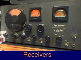
Receivers
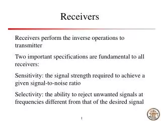
Receivers. Receivers perform the inverse operations to transmitter Two important specifications are fundamental to all receivers: Sensitivity: the signal strength required to achieve a given signal-to-noise ratio

Receivers
E N D
Presentation Transcript
Receivers Receivers perform the inverse operations to transmitter Two important specifications are fundamental to all receivers: Sensitivity: the signal strength required to achieve a given signal-to-noise ratio Selectivity: the ability to reject unwanted signals at frequencies different from that of the desired signal
Receiver topologies Three receiver configurations Head phones Detector RL Un-tuned Head phones Detector Detector Speaker RL RL Tuned Amplified
Tuned radio frequency(TRF) receiver Detector Speaker RL B = f / Q Q = XL/ R Thus the bandwidth varies with the square root of frequency A 10kHz bandwidth would become 17kHz when tuning from 540kHz to 1700kHz
Super-heterodyne receiver To solve the problem of varied bandwidth, the super-heterodyne receiver is proposed BPF BPF BPF Detector Speaker AGC LO The local oscillator is tunable, so the intermediate frequency (IF) is fixed regardless of the signal frequency
Super-heterodyne receiver components Converter LO The BW of the filter can be fixed BPF Example: Signal frequency: 540kHz, LO: 540 + 455 = 995 kHz Signal frequency: 1700kHz, LO: 1700 + 455 = 2155 kHz
Optical-heterodyne receiver See the PTL paper
Receiver block diagram Autodyne converter Detector Speaker AGC The mixer and LO use a single transistor in a configuration called an autodyne converter
High side and low side injection High side injection: the LO is tuned so that it generates a frequency that is always 455kHz higher than the incoming signal frequency Low side injection: the LO is always 455kHz lower than the signal frequency. Percentage wise, the LO has to have a wider tuning range
Receiver characteristics Sensitivity: The ability to receive weak signals with an acceptable signal-to-noise ratio (S/N) is called sensitivity. It is expressed in terms of the voltage or power the the antenna necessary to achieve a specified SNR One common specification for AM receivers is the signal strength required for a 10dB (S+N)/N ratio
Selectivity The ability to discriminate against interfering signals is known as selectivity The ratio between the B-60dB and B-6dB is called the shape factor Adjacent channel rejection Alternate channel rejection B-6dB B-60dB
Distortion Harmonic distortion – when the frequencies generated are multiples of those in the original modulating signal Inter-modulation distortion – when frequency components mix in a nonlinear device Un-even frequency response Phase distortion – irregular phase shift rather than linear phase shift that increases with frequency
Dynamic range The response to weak signal is usually limited by noise Signals that are too strong will overload one more more stages The ratio between these two signals levels is the dynamic range of the receiver In many receivers the dynamic range is actually the AGC range
Spurious responses Image frequencies Signal LO Image Image LO Signal High side injection Low side injection An image must be rejected prior to mixing
Demodulators Full-carrier AM: envelope detector Out Fig. 6.11 envelope detector
SSBSC AM SSB or DSBSC LPF LO V0 = sin(ωct) x cos(ωc + ωm)t = 0.5 [sin(- ωm t) + sin(2 ωc + ωm)t]
Impact of frequency offset For SSB, the impact is relatively small For DSBSC, the offset may cause significant degradation of the the signal Would be a good study to try out
FM demodulation kd = Vo / δ kd is the detector sensitivity Vo is the output voltage δ is the frequency deviation S-curve of the FM detector
Slope detector The simplest FM demodulator is a slope detector f