Advanced Integrated Receivers for Data Transport Systems
This program aims to develop cost-effective, compact, and reliable receivers integrating RF to baseband, analog to digital, and copper to fiber conversions, enhancing data transmission stability.

Advanced Integrated Receivers for Data Transport Systems
E N D
Presentation Transcript
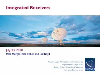
Integrated Receivers • July 23, 2010 • Matt Morgan, Rick Fisher, and Tod Boyd
Analog/Digital/Photonic Receiver Program • To develop receivers and wide bandwidth data transport systems which are lower cost, more compact, more reliable, lower weight, more reproducible, and more stable than the best current systems. • To integrate the conversions from RF to baseband, from analog to digital, and from copper to fiber into a single compact package. • To digitize the signal as close to the antenna feed as possible • this inevitably involves transferring some functionality from analog hardware to the digital domain.
Three-Probe Planar OMT With Integrated LNAs • The incoming signals from some arbitrary number of probes in a circular waveguide are digitized independently and recombined with calibrated weighting coefficients to synthesize accurate polarizations. • Corrects for all amplitude and phase errors of the probe geometry as well as the receiver chains attached to them. • Prototypes shown at the left are for X-Band (8-12 GHz)
DOMT Gain Matrix Representation • Gain matrix relates sky signal vector to output voltage vector: • or • where
Moore-Penrose Pseudo-Inverse Provides a Least-Squares Fit • Direct inversion is not possible (unless N=2), but we can estimate • where
Polarization Results Isolation (Linear) Axial Ratio (Circular)
Flex Ribbon Thermal Transition • copper traces on 5-mil thick Kapton substrate • lithography sufficient for 3 mm band application • easy to parallelize • smaller, lighter, and cheaper than stainless steel coax or waveguide • shorter (physically and electrically) for the same thermal isolation
Predicted Results: 15-300K Transitions for 50 Dual-Polarized Beams… *Not including the flanges, or the extra height of the dewar.
Digital Sideband Separating Mixer With Integrated ADCs L-Band Module Digital Outputs Analog Inputs Analog Side Digital Side ADCs IF Channels RF Board
Digital Sideband-Separating Mixer (DSSM) • I- and Q-channels digitized and recombined with calibrated complex weighting coefficients. • Corrects for LO, RF, and IF analog amplitude and phase errors. • Extremely stable design: 50 dB sideband-suppression without re-calibration over a 12 °C temperature change. • No increase in digital data rate: requires two ADC's with half the sample rate for a given processed bandwidth. 28°C 40°C
Designed for Calibration Stability • Short electrical paths, elimination of standing waves, and the lack of intermediate cabling and connectors lead to smooth, stable complex gain curves. • Sideband suppression >52 dB in the passband. • Measurement performed six days after calibration. • Only calibrated 10 points across the band – 80% of the points shown use interpolated calibration coefficients.
Internal ADCs Introduce No Measurable Interference expected clock harmonic (12.5 minute integration)
LNA Design and Construction at the CDL • July 23, 2010 • Matt Morgan, Rick Fisher, and Tod Boyd
Band 6 IF Amplifier Fabrication • Resistors, capacitors, and substrates installed by an outside vendor (Advanced Control Components) • CRYO3 FETs from NGST and MAP FETs from HRL installed here • Final tuning and pair-matching is performed here with cold-testing by an experienced technician in the Band 6 group (Mike Lambeth). • Similar units and techniques used for EVLA production...
New MMIC Designs in Fabrication • Eric has also developed LNA designs for 67-95 GHz and 68-116 GHz bandwidths. • We are also experimenting with hybrid approaches: • MMIC partial-LNA with an off-chip quartz matching network • discrete-FET first-stage plus MMIC second-third-fourth-stage