Advanced Radio Receiver Functions and Characteristics
Explore how a receiver selects, amplifies, and demodulates signals while overcoming noise, drift, and interference. Learn about receiver top attributes like selectivity, sensitivity, and stability. Discover various receiver types and their unique features.
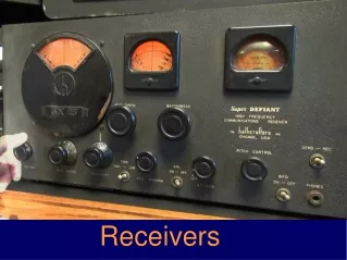

Advanced Radio Receiver Functions and Characteristics
E N D
Presentation Transcript
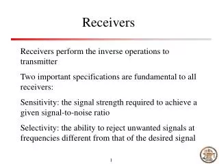
The Receiver’s Task The Antenna responds to the Radio Waves and delivers signals. The desired Signal must be Selected from unwanted signals. The desired Signal must be Amplified to useful levels. The desired Signal must be Demodulated to baseband audio. The audio signal may need to be Processed in some way. The Audio Signal may require more Amplification. Receiver Top Attributes Selectivity Sensitivity Stability
Selectivity Selectivity defines the bandwidth of the receiver, controlling what frequencies are passed to the demodulation process. The optimum bandwidth depends upon the signal mode, and the presence of adjacent channel interference. NBFM 15 kHz PSK-31 150 Hz WBFM 150 kHz SSB 3 kHz ~ 1.8k Hz AM 6~10 kHz / 5 kHz JT65A 250 Hz CW 500 Hz ~ 80 Hz
Sensitivity Noise, both Man Made and Natural limit the ability to receive radio signals. Amplification of weak signals also adds noise due to the random thermal movement of charge carriers. On the bench a typical receiver can detect a 0.2V signal, but the noise on HF is usually much higher.
Johnson–Nyquist noise (thermal noise, white noise, Johnson noise, or Nyquist noise) is the electronic noise generated by the thermal agitation of the charge carriers (usually the electrons) inside any electrical conductor at temperature equilibrium, which happens regardless of any applied voltage.
Thermal Noise is a limiting factor in communication systems. Bigger antennas and lower loss transmission lines collect more signal and increase the signal to noise ratio, making the difference between hearing a station, or not.
Stability Once tuned to a frequency we expect a receiver to stay on that frequency. Drift, a slow change in frequency, will originate in the local oscillators that control the received frequency. Drift is usually due to changes in the dimensions of the tuning components caused by the heat of components and the currents flowing in coils and capacitors.
A Simple Crystal Radio The single tuned circuit provides limited selectivity and poorly limits receive response to nearby radio stations. Drift is not an issue when the bandwidth is 50 kHz or more. The Diode Detector rectifies the received radio energy, and high impedance headphones are required to hear the weak signal. A longer antenna and better ground improves received signal strength.
Edwin Armstrong explains his Super-Regenerative Receiver
Single Tube Regenerative Receiver from post WWII ARRL Handbooks, developed by Edwin Armstrong.
Superheterodyne Mixer Any Non-Linear device will mix two signals to create Sum and Difference signals, as well as the originating signals.
Direct Conversion Receiver Carrier Modulation creates sidebands on either side of the carrier. In a Direct Conversion or Synchrodyne Receiver a local oscillator is tuned to the carrier frequency and Hetrodynes the sidebands directly to audio frequencies. A low noise audio amplifier brings the signals to sufficient strength for headphones or a speaker. Both Upper and Lower Sidebands are demodulated, which may create interference if the band is crowded with signals.
Hartley Oscillator, Dual Diode Detector, low pass filter, audio amp.
Neophyte Receiver QST Feb 1988 Direct Conversion 40m version shown. Inductors are Green core 10.7MHz IF transformers, or purpose wound Toroid coils. Specs are 0.5V across 50, BW of 7.5kHz, ½ watt audio out.
The Signetics NE602 contains a Colpitts oscillator on pins 6 & 7 and a balanced active mixer which hetrodynes incoming signals to audio. The LM386 amplifies the audio to headphones. Audio Bandwidth is very wide and gives the impression of listening directly to the radio spectrum, due to the low internal noise. Designed by Iulian Rosu, VA3IUL of Waterloo, Ont.
The AM Superheterodyne Receiver The RF amplifier sets the receiver noise level and compensates for Mixer Losses. The L.O. and Mixer convert received signal to the IF, where most of the selectivity and signal amplification occurs. The Diode Detector rectifies the Amplitude Modulated carrier to Audio plus a DC voltage from the carrier which is used for AGC to control the gain of the IF stage and often the gain of the RF Amp.
Circa 1954 five tube superhetrodyne receiver with AM band, three short wave bands, and a feedback type BFO for CW.
The Beat Frequency Oscillator Single Sideband Suppressed Carrier and Continuous Wave signals do not have a Carrier Wave for a diode detector to hetrodyne. A Beat Frequency Oscillator is required to create a substitute carrier to convert the I.F. signal to audio. The BFO may be tuneable, as in post war receivers, crystal controlled or synthesized in the frequency tuning circuits.
A Simple Superhet Receiver NE602 Front End mixer, Crystal Filter & NE602 BFO Product Detector. Room for a T-R Switch by the antenna.
Designed as a single fixed frequency receiver for 20m beacons.
Dual Conversion Block Diagram Front End Pre-Selector passes a narrow band to the RF amplifier. Crystal Controlled Band selection mixes a 500 kHz chunk to a mid frequency IF. A tuneable second local oscillator mixes the 1st IF to a second narrow IF, tuning across the 500 kHz. The receiver selectivity and gain is in the second IF. A crystal controlled BFO and Product Detector convert the IF to audio, with switchable Sideband selection.
Up Converting Superhet Receiver Up conversion moves the Image Range into the VHF, which a 30 MHz low pass front end filter easily removes. The VHF Local Oscillator tunes 70 MHz above the receive frequency. The 1st IF sets a wide bandwidth “Roofing Filter” which limits out of band signals. The 2nd Local Oscillator and mixer converts the 1st IF to the 2nd IF, where all of the narrow band selectivity is defined. The 9 MHz filters may be switchable. The BFO and product detector converts the 9 MHz IF to audio, followed by an audio low pass filter and audio amplifier.
Intermediate Frequency Filters Multiple Crystal Filters provide flexibility to chose an optimum bandwidth to match receive conditions and modes. Each filter can be $100 to 250. This is a Yaesu FT-1000-MP
Crystal IF Filters Transmission Bandwidth -6dB Stop Bandwidth -60 dB Insertion Loss Pass Band Ripple Shape Factor Stop Band Rejection
Collins Mechanical Filters A Magnitostrictive or Piezoelectric Transducer converts an electrical signal into a mechanical movement which is coupled into either disk or rod resonators. These resonators vibrate only at the I.F. frequency, passing the signal to the output. Mechanical filters are most often at 455 kHz and sometimes at lower frequencies, like 260 kHz.
Crystal Controlled Dual Conversion tube receiver, still a favourite of DXers and rag chewers.
Dynamic Range All amplifiers will begin to produce signal harmonics as the signal level increases. The 3rd harmonic is particularly troublesome. When the level of 3rd harmonic is equal to the signal level this is called the 3rd Order Intermodulation Distortion Point. Higher is Better.
Digital Signal Processing Receiver An Upconverting Front End provides some RF gain, selectivity and AGC control. Instead of an IF system the signal is digitized (32Bit) and then processed with software filters and demodulation. Software filters allow almost infinite choice of bandwidth, from 15 kHz for FM on 10m &6m to an ultra narrow 80 Hz for CW. Literally everything in the receive and transmit path is configurable, which can be quite overpowering and confounding at first. Digital Noise Blankers can be trained to completely ignore repetitive signals and man made noises.
Yaesu FT-950 DSP Receiver No question the best receiver I’ve ever owned. Flexible, easily learned, dual VFOs, easy split operation. Stable. Affordable.
Yaesu FT-5000 This, or a second car. My wife won that one. $6000 plus acc. Too much Radio? Could you afford to turn it off? Think of the operating time you would miss by eating, sleeping, working. D.R.=112 dB, 3rd IMD +40dBm, two 32Bit DSP receivers, 200W
DDS Receiver The Direct Digital VFO chip, like the Si570, creates a clock at 4 times the receive frequency. This signal is digitally divided by 4 to create two signals that are 90o out of phase. These quadrature signals drive balanced mixers to create the I and Q audio signals that contain all frequency, amplitude and phase information for the RF passband. The DDS receiver relies upon the Audio to Digital conversion in the computer Sound Card. High Sampling Rate and Bit Depth are required for wider received Bandwidth and Dynamic Range.
USB Dongle SDR European Digital TV to USB receiver. Uses the Elonics E4000EQ6 Covers 25 MHz to 1700 MHz, all modes. Cost: $16.65 Buy it Now Check out “Nooelec” and other bargains.
RXTX Ensemble by Tony Parks KB9YIG Built for 2 ~ 3 bands Software Defined Receiver and Softward Defined Transmitter 1W Uses mostly through hole construction. $90 as kit.
The Surface Mount components and fine lead spacing makes for challenging soldering, but it is very do-able with care and some learning.
DDSVFO Microprocessor
Q I