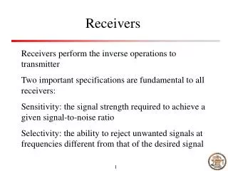
Radio Receivers
Radio Receivers. EC 326 COMMUNICATION SYSTEMS UNIT – I Part II. T Srinivasa Rao Dept. of ECE Bapatla Engineering College. Main Functions. Intercept the electromagnetic waves in the receiving antenna to produce the desired R.F. modulated carrier.

Radio Receivers
E N D
Presentation Transcript
Radio Receivers Communication Systems ( EC-326)
EC 326 COMMUNICATION SYSTEMSUNIT – IPart II T Srinivasa Rao Dept. of ECE Bapatla Engineering College Communication Systems ( EC-326)
Main Functions Intercept the electromagnetic waves in the receiving antenna to produce the desired R.F. modulated carrier. Select the desired signal and reject the unwanted signals. Amplify the R.F. signal Detect the RF carrier to get back the original modulation frequency voltage . Amplify the modulation frequency voltage. Communication Systems ( EC-326)
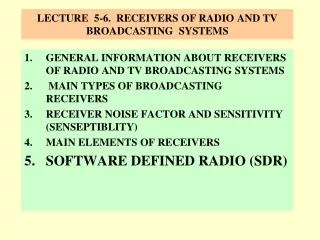
Classification AM. (Amplitude Modulation) Broadcast Receivers. F.M. (Frequency Modulation) Boadcast Receivers. T.V. (Television) Receiver. Communication Receivers. Code Receivers. Radar Receivers. Communication Systems ( EC-326)
Features Simplicity of operation. Good Fidelity. Good Selectivity. Average Sensitivity. Adaptability to different types of Aerials. Communication Systems ( EC-326)
A M Receivers Communication Systems ( EC-326)
Basic Functions of A M Receivers Reception. Selection. Detection. Reproduction. Straight Receivers Superheterodyne Receiver. Communication Systems ( EC-326)
Noncoherent Tuned Radio-Frequency Receiver Antenna coupling network RF amp. RF amp. RF amp. • Difficult to tune • Q remains constant filter bandwidth varies Audio detector Audio amplifier Nonuniform selectivity Communication Systems ( EC-326)
? • For an AM receiver commercial broad cast band receiver (535KHz to 1.605MHz) with an input filter Q factor of 54 , determine the bandwidth at the low and high ends of RF spectrum Communication Systems ( EC-326)
Band width at low frequency Band width at high frequency -3dB band width at low frequency is 10KHz but at high frequency 3 times that of the low frequencies. Tuning at high end of the spectrum three stations would be received simultaneously. To achieve band width of 10KHz at high frequencies a Q of 160dB is required but with a Q of 160 the band width at low frequencies is It is too selective and band rejection will takes place. Communication Systems ( EC-326)
Super Heterodyne Receiver Mixer / Converter Section Mixer RF Section IF Section Pre selector RF amplifier Band pass filter IF Amplifier IF signal RF signal Local Oscillator Gang tuning Audio amplifier Section Audio detector Section Audio Amplifier AM Detector speaker Audio Frequencies Communication Systems ( EC-326)
TRF - non uniform selective Gain Selectivity Sensitivity Heterodyne receiver Heterodyne Mix two frequencies together in a non linear device. Translate one frequency to another using non linear mixing Heterodyne receiver has five sections Communication Systems ( EC-326)
RF section Mixer / converter section IF section Audio detector Section Audio amplifier Section Communication Systems ( EC-326)
RF Section Amplifier stage Pre-selector It determines the sensitivity of the receiver. Broad tuned band pass filter with adjustable frequency that is tuned to carrier frequency RF amplifier is the first active device in the network it is the primary contributor to the noise. And it is the predominant factor in determining the noise figure. Receiver may have one or more RF amplifier depending on the desired sensitivity. Reduces the noise bandwidth of the receiver and provides the initial step toward reducing the over all receiver bandwidth to the minimum bandwidth required to pass the information signal. Provide initial band limiting to prevent specific unwanted radio frequency called image frequency from entering into receiver. Due to RF amplifier Greater gain and better sensitivity Improved image frequency rejection Better signal to noise ratio Better selectivity. Communication Systems ( EC-326)
RF Amplifier Communication Systems ( EC-326)
Demodulation process: High frequency signal Frequency translation IF source information RF IF RF for commercial broadcast purpose AM broadcast band 535 – 1605 KHz and IF 450 – 460 KHz. 88 – 108 MHz and IF 10.7MHz FM broadcast band Communication Systems ( EC-326)
MIXER OR CONVERTER SECTION Local oscillator Mixer Mixer stage is a nonlinear device Radio frequencies are down converted to intermediate frequency Convert radio frequencies to intermediate frequency Carrier and sidebands are translated to high frequencies without effecting the envelope of message signal. Heterodyning takes place in the mixer stage. Communication Systems ( EC-326)
Frequency conversion Similar to that of modulator stage Frequencies are down converted. Frequency conversion The difference between the Rf and Local oscillator frequency is always constant IF The adjustment for the center frequency of the preselector and the adjustment for local oscillator are gang tuned. The two adjustments are mechanically tied together and single adjustment will change the center frequency of the pre selector and the local oscillator Communication Systems ( EC-326)
Low side injection High side injection Local oscillator frequency is tuned above RF Local oscillator frequency is tuned below RF f LO = fRf - fIF f LO = fRf + fIF Communication Systems ( EC-326)
Receiver RF input (535 – 1605 kHz) RF-to-IF conversion Preselector 535 - 565 kHz 535 545 555 565 kHz Mixer Oscillator 1005 kHz high-side injection (fLO > fRF) 440 450 460 470 kHz IF filter 450 – 460 kHz IF Filter output 450 460 kHz Communication Systems ( EC-326)
Frequency Mixer and Oscillator Communication Systems ( EC-326)
Frequency Conversion Communication Systems ( EC-326)
535 540 545 550 555 560 565 470 440 445 450 455 460 465 Channel 1 Channel 2 Channel 3 450 455 460 Communication Systems ( EC-326)
For an AM super heterodyne receiver that uses high side injection and has a local oscillator frequency of 1355KHz determine the IF carrier upper side frequency, and lower side frequency for an RF wave that is made up of a carrier and upper and lower side bands 900 and 905 and 895KHz respectively Communication Systems ( EC-326)
895 900 905 In KHz ch-2 Mixer / Converter Section RF Section IF Section Pre selector RF amplifier Band pass filter IF Amplifier Local oscillator • 455 460 • In KHz ch-2 Ganged tuning Communication Systems ( EC-326)
LOCAL OSCILLATOR TRACKING: TRACKING: It is the ability of the local oscillator in a receiver to oscillate either above or below the selected radio frequency carrier by an amount equal to the IF frequency through the entire radio frequency band. High side injection: Local oscillator frequency frf+fif Low side injection: Local oscillator frequency frf-fif Communication Systems ( EC-326)
Tracking Communication Systems ( EC-326)
PRESELECTOR AND LOCAL OSCILLATOR Preselector Tuned circuit Preselector RF output Gang tuning Ls LO output frequency Local oscillator tuned circuit Lp Ls Ct Lp Lp Co Ct Co TRACKING CURVE Three point tracking Poor tracking Ideal tracking Communication Systems ( EC-326) 600 800 1000 1200 1400 1600
The tuned ckt in the preselector is tunable from the center frequency from 540KHz to 1600 KHz and local oscillator from 995KHz to 2055KHz.( 2.96 to 1) Tracking error: the difference between the actual local oscillator frequency to the desired frequency. The maximum tracking error 3KHz + or -. Tracking error can be reduced by using three point tracking. The preselector and local oscillator each have trimmer capacitor ct in parallel with primary tuning capacitor co that compensates for minor tracking errors in the high end of AM spectrum. The local oscillator has additional padder capacitor cp in series with the tuning coil that compensates for minor tracking errors at the low end of AM spectrum. With three point tracking the tracking error can be adjusted from 0Hz at approximately 600KHz, 950KHz AND 1500KHz Communication Systems ( EC-326)
Image frequency : It is any frequency other than the selected radio frequency carrier that is allowed to enter into the receiver and mix with the local oscillator will produce cross product frequencies that is equal to the intermediate frequency. flo =fsi+fif → fsi=flo-fif when signal frequency is mixed with oscillator frequency one of the by products is the difference frequency which is passed to the amplifier in the IF stage. The frequency fim= flo+fsi the image frequency will also produce fsi when mixed with fo . For better image frequency rejection a high IF is preferred. If intermediate frequency is high it is very difficult to design stable amplifiers. Communication Systems ( EC-326)
2fif fif fif IF RF SF LO im frequency Communication Systems ( EC-326)
Image frequency rejection ratio It is the numerical measure of the ability of the preselector to reject the image frequency. Single tuned amplifier the ratio of the gain at the desired RF to the gain at the image frequency. If multiple amplifiers are there the IFRR is nothing but the product of IFRRs of the individual stages. Communication Systems ( EC-326)
? • In a broadcast superheterodyne receiver having no RF amplifier, the loaded Q of the antenna coupling circuit (at the input of the mixer ) is 100. If the intermediate frequency is 455kHz, calculate the image frequency and its rejection ratio at(a) 1000 kHz and (b) 25 MHz. Communication Systems ( EC-326)
For an AM broad cast band super heterodyne receiver with If, RF, LO frequencies are 455KHz, 600KHz, 1055KHz determine • Image frequency • IFRR for a preselector Q of 100 • Fim = flo+fif • Fim = frf+2fif • Fim= 1510 kHz. • ρ= 2.113 • IFRR= 211.3 Communication Systems ( EC-326)
For citizens band receiver using high side injection with an RF carrier of 27MHZ and IF center frequency of 455KHz determine • LO frequency • Image frequency • IFRR for a preselector Q of 100 • Preselector Q required to achieve the same IFRR as that achieved for an RF carrier of 600KHz input. • Ans: • 27.455MHz • 27.91MHz • 6.77 • 3167. Communication Systems ( EC-326)
Double spotting : it occurs when the receiver picks up the same station at two near by points on the receiver tuning dial. It is caused by poor front end selectivity and inadequate image frequency rejection. Weak stations are overshadowed. Communication Systems ( EC-326)
Choice of IF : Factors If the IF is too high • Poor Selectivity and Poor adjacent channel rejection. • Tracking Difficulties. If the IF is too low • Image frequency rejection becomes poorer. • Selectivity too sharp and cutting off sidebands • Instability of oscillator will occur. Communication Systems ( EC-326)
Frequencies Used • Standard broadcast AM : 455 kHz (465 kHz). • AM,SSB ( shortwave reception ) is about 1.6 -2.3 MHz • FM (88-108 MHz): 10.7 MHz. • Television Rx: ( VHF band 54-223MHz and UHF band 470-940 MHz): Between 26 and 46 MHz. • Microwave and RADAR ( 1-10GHz): 30,60,70MHz. Communication Systems ( EC-326)
IF AMPLIFIER Communication Systems ( EC-326)
Detector and AVC Communication Systems ( EC-326)
Tone Compensation Volume Control Communication Systems ( EC-326)
Detector using Transistor Communication Systems ( EC-326)
Tone Control Communication Systems ( EC-326)
Tuning Control Communication Systems ( EC-326)
Example IFRR = 211.3 Q (600 kHz) = 100 (Simple preselector) Low Q 455 kHz 1055 600 1510 IF RF LO Image Communication Systems ( EC-326)
Example IFRR = 211.3 Q (27 MHz) = 3167 Q (600 kHz) = 100 Low Q High Q 27.455 455 kHz 1055 27 MHz 600 1510 27.91 IF RF LO Image RF LO Image Solution: Use higher IF frequencies Communication Systems ( EC-326)
Gain and Loss RF-section Mixer Preselector RF amplifier oscillator Bandpass filter IF amplifier Audio detector Audio amplifier IF-section Use dB !!! Communication Systems ( EC-326)
Envelope detector or Peak detector D IF-in Audio out R C ? Communication Systems ( EC-326)
Envelope detection D IF-in Audio out R C Communication Systems ( EC-326)