Download
1 / 11
110 likes | 192 Vues
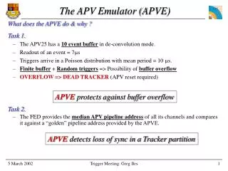
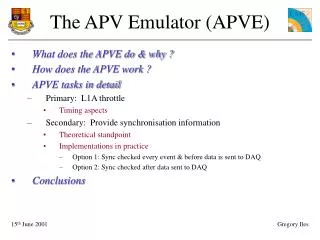
The APV Emulator (APVE). What does the APVE do & why ? How does the APVE work ? APVE tasks in detail Primary: L1A throttle Timing aspects Secondary: Provide synchronisation information Theoretical standpoint Implementations in practice

E N D
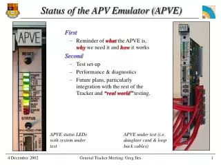
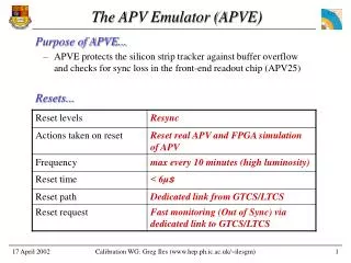
The APV Emulator (APVE) • What does the APVE do & why ? • How does the APVE work ? • APVE tasks in detail • Primary: L1A throttle • Timing aspects • Secondary: Provide synchronisation information • Theoretical standpoint • Implementations in practice • Option 1: Sync checked every event & before data is sent to DAQ • Option 2: Sync checked after data sent to DAQ • Conclusions
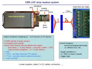
What does APVE do & why ? L1A • L1A throttle • Asserts BUSY to TTS if the next L1A would make the APV buffers overflow. • Sync check • Provides information to ensure APVs are sending the correct data for a given event. TTS inhibit gate BUSY L1A APV Emulator APV Pipeline address or time check APV data frame FED APVs in sync (i.e sending correct data for event)
How does APVE work ? L1A All fast signals L1A, RESET & CAL • L1A Throttle • A counter keeps track of the number of filled APV buffers • L1A increments buffer • APV frame output signal indicates that a buffer has emptied and thus the counter is decremented • If counter indicates APV buffers full it asserts BUSY. • Synchronisation check • Header on APV data frame provides pipeline address • Frame arrival time also provides sync check APV APV data frame Header recognition & storage UP Frame output signal Buffer counter DOWN Pipeline address Max buffer Size from VME Buffers full ? BUSY
L1A throttle • Primary task of emulator • Will only inhibit L1A coming from TTS, not those from Tracker Control • Timing critical • Set by control loop • Ideally need to assert BUSY before next L1A passes through TTS inhibit gate (i.e. < 75ns) • Alternatively we lose an event buffer location in the APV for every 75ns delay. • Net consequence is that the APV dead time increases. • Ideally also want L1A only line. L1A RESET (S/H) CAL Tracker Control TTS inhibit gate Fast Control Generator ‘101’ RESET, ’11’ CAL & L1A L1A BUSY Fast Control Merge L1A only ? All fast signals APV Emulator TTCvi
Possible control structure… • Possible control structure • There are 4 L1A inputs to the TTCvi. We could therefore switch between TTS & Tracker Control trigger line • Switching between TTS & Tracker Control trigger line takes place under software control & therefore slowly • Is this OK ? L1A RESET (S/H) CAL Tracker Control TTS inhibit gate Orbit SESQI ? ‘101’ RESET, ’11’ CAL & ‘1’ L1A L1A BUSY TTCvi ? VME Write TTS or Tracker Control APV Emulator TTC System
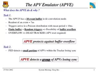
Individual APV sync loss • Secondary task of emulator • Detect APVs losing sync • individually (e.g. SEU) • in a group (e.g. system failure) • Individual APV sync loss • Each front-end FPGA automatically detects and disables APVs that: • are out of time sync with ‘nearest neighbours’ • have a different pipeline address to the median of the ‘nearest neighbours’. • Median pipeline address sent to back-end FPGA with list of APVs that are out of sync. median pipeline addresses & list of out of sync APVs Front-end FPGA #1 2x12 APVs #1 Front-end FPGA #2 2x12 APVs #2 Back-end FPGA Front-end FPGA #8 2x12 APVs #8
Group sync loss… Theory • Group APV sync loss (e.g. system failure in CCU-PLL ring or FEC ?) • Should be rare (or the Tracker lifetime is very short !) • Need to perform sync check against a global variable • Pipeline address of data frame • Time at which APV data frame arrives • Two possible options ………. • On every event check if APVs in sync before sending data to DAQ L Timing critical or buffers will overflow JEnsures that all data post FED is in sync • Check if APVs in sync after sending data to DAQ, but send front-end FPGA median pipeline address with data so DAQ can check it (if needed) LCorrupt data will be sent to DAQ %Responsibility for checking data integrity shifted to DAQ JWill only happen rarely and for short period JDon’t need to check every event
Group sync loss… Option 1 • Sync checked every event and before data sent to DAQ • Pipeline address sent from emulator to FED via B channel on TTCvi using TRIGGER TYPE input. LModification of TTCvi needed to latch TRIGGER TYPE a variable time (up to 200us) after L1A has passed through TTCvi N Timing critical because of race between APV data frames from the Tracker and the pipeline address sent by the emulator. • Use separate TTC branch to distribute delayed L1A to FEDs. Delayed L1A produced on output of data frame from emulator APV. Optionally, the pipeline address could be sent via the TTCvi TRIGGER TYPE input because the pipeline address would be known at this stage. LUgly solution because it requires second TTCvi branch NDAQ will fail to OK event because The TTCrx will generate the wrong bunch crossing number
Group sync loss… Option 2 • Sync checked after data sent to DAQ • Check could either be performed in FED or in the Tracker Control monitoring PC. L Need to make sure that you store that the pipeline address from the same event in the emulator and FEDs. L Check ought to happen every few seconds, regardless of trigger rate.
Conclusions • Welcome feedback • Main issue has always been how we get global address check to FED • At present intend to check data after it has been sent to DAQ at a frequency of every few seconds and in software • Outstanding issues • Where does merge of fast feedback signals, such as BUSY, take place, if at all ? (see talk by Costas) • APVE needs to be the last stage in this process, or very near it because timing critical for L1A throttle • At present APVE design incorporates 5 NIM inputs that are OR’ed with APVE fast feedback signals • Plans for the future • Publish document on APVE ? • Produce time schedule for design, fabrication & testing
The pipeline address race… TTS out TTCvi/APVE in APV (APVE) out Pipeline latched (APVE) APV (Tracker) out TRIGGER TYPE latched (TTCvi) B channel TTCvi, B<1> B channel TTCvi, B<0> (inhibit) B channel TTCvi, B<0> (short) TRIGGER TYPE + EVENT # Pipeline latched by FED TTCrx APV Frame arives @ FED Tracker pipeline latched @ FED