Download
1 / 18
180 likes | 320 Vues
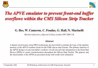
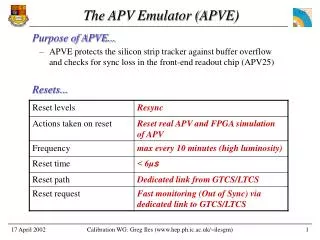
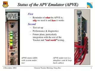
Status of the APV Emulator (APVE). First Reminder of what the APVE is, why we need it and how it works Second Test set-up Performance & diagnostics Future plans, particularly integration with the rest of the Tracker and “real world” testing. APVE status LEDs with system under test.

E N D
Status of the APV Emulator (APVE) • First • Reminder of what the APVE is, why we need it and how it works • Second • Test set-up • Performance & diagnostics • Future plans, particularly integration with the rest of the Tracker and “real world” testing. APVE status LEDs with system under test APVE under test (i.e. daughter card & loop back cables) General Tracker Meeting: Greg Iles
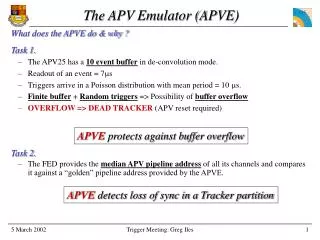
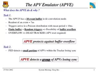
Task 1. The APV25 has a 10 event buffer in de-convolution mode. Triggers arrive in a Poisson distribution with........ Max rate = 1 event every 75 ns Mean period = 10 s Readout of an event = 7000 ns Finite buffer + Random triggers => Possibility of buffer overflow BUFFER OVERFLOW => APV reset required Task 2. The FED provides the median APV pipeline address of all its channels and compares it against a “golden” pipeline address provided by the APVE. The APV Emulator (APVE) What does the APVE do & why ? APVEprotects against buffer overflow APVEdetects loss of sync in a Tracker partition General Tracker Meeting: Greg Iles
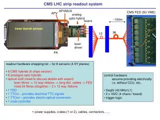
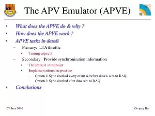
What does the APVE do & why ? • Primary task: Preventing buffer overflow in APVs • Its takes too long to send a ‘buffers full’ signal from APVs in the tracker to Trigger Control System (TCS). • Therefore require an APV close to the TCS. • Secondary task: Synchronisation check • All APV data frames include the memory cell (pipeline) address used to store the L1A data in the APV. • The pipeline address is sent to all FEDs to ensure that all APVs are in-sync. Reset and L1A (min period = 75ns) TCS: Inhibit L1A? Busy Tracker APVE APV in deconvolution mode 1: Full 2: Full 3: Empty Pipeline address 10: Empty Data frame (period = 7000ns) FED: Data OK? General Tracker Meeting: Greg Iles
Control structure • Control & Feedback Structure....... • APVE receives Clk, BC0, L1A, L1Reset from Central & Local TCS • APVE user selects CTCS, LTCS or neither via VME (i.e. just like TTCci) • APVE sends Warn, Busy, Out-Of-Sync, Ready etc to Central & Local TCS • Sync Check info for FED • Pipeline address transmitted to FED via TTCci B channel. CTCS LTCS APVE TTCci/ex/tx FEC FMM CCU Ring Other FEDs APV Reset & L1As Fast feedback Pipeline address FED Data General Tracker Meeting: Greg Iles
APVE test set up VME (A24/D16) to Wishbone bridge All modules connected within FPGA via Wishbone bus APVE ( ) and APVE tester modules ( ) are all contained within the single FPGA on the APVE. TCS Control Clk, L1A, L1Reset, BC0, ECR, OCR Useful in test beams ? optional ext trigger Reports status of APV emulator and FMM input to TCS Trigger Control System CENTRAL Ethernet cables connecting APVE signals to APVE tester daughter card optional ext trigger Trigger Control System LOCAL FMM Tester APVE Status READY, ERROR, etc FMM Status General Tracker Meeting: Greg Iles
APVE and daughter test card LEDs APV25 daughter card Switch to display either APV, FMM or merged status All logic in Xilinx 1M gate Virtex2 FPGA Synchronisation info (pipeline address) sent to TTCci Central & Local TCS in Daughter test card that that connects to the FPGA and allows us to emulate the TCS and FMM in testing Central & Local TCS out FMM in General Tracker Meeting: Greg Iles
L1As filling APV buffers 2) When TCS receives READY it enables L1As. 3) Buffer counter increases by 3 for each L1A because we are in deconvolution mode • 6) Time lag in • - BUSY reaching TCS • L1As reaching APVE • => L1As continue after BUSY asserted Buffers L1As Status 4)WARN asserted 5)BUSY asserted. 1)READY asserted after L1Reset (not shown) Pipeline address General Tracker Meeting: Greg Iles
L1As enabled as buffers empty 2) Number of filled buffers drops from 20 to 19 4) TCS responds by enabling L1As • 6) Again time lag in • - BUSY reaching TCS • L1As reaching APVE • => L1As continue after BUSY asserted 1) An APV buffer is emptied Buffers L1As Status 3) APVE status switches from BUSY to WARN 5) APVE immediately asserts BUSY Pipeline address General Tracker Meeting: Greg Iles
APVE under test Test system running at extremes. - L1A rate = 1 every 3 clks - Full APV buffer capacity used System tested with Central & Local TCS. APV in peak and deconvolution. Virtual & Real APV traces are displayed on the scope to visually check APVs in sync. System then pushed beyond limits. - Buffer level at which BUSY asserted increased. Check system switches to OOS TCS selected - Central or Local Systems enabled - APV, FMM or both L1Reset & L1A System switching between “WARN” & “BUSY” Status of APV, FMM or that being sent to TCS (merge). Selectable by switch (i.e.READY, WARN, etc) General Tracker Meeting: Greg Iles
All functionality in single Xilinx Virtex2, 1M gate FPGA VME to Internal FPGA bus (Wishbone) I2C Interface for real APV Implementation of APV buffer logic to create a Virtual APV. Built in TCS & FMM test units which are programmable via software. Diagnostics A series of registers and memories coupled with an “intelligent” response from the APVE should make it simple to diagnose why the system is OOS (Out-Of-Sync) or in ERROR. The APVE contains circular memories that record Any change in output status and the orbit number / bunch crossing number that this occurs (4k deep) The synchronisation information for each event (2k deep) Functionality General Tracker Meeting: Greg Iles
Performance • Performance • The size of the control loop ( ) from TCS-APVE-TCS must be kept to a minimum to ensure a high Tracker efficiency. • The response time of the APV part of the APVE is 1 clk cycle. • The VHDL simulation of the APV logic within the FPGA provides knowledge of the APV internal buffers thus achieving maximum Tracker efficiency. • The APVE resides in the same rack as the Central TCS thus keeping cable delays to a minimum • Reliability • System has been running for days/weeks at the maximum trigger rate in both peak and deconvolution mode. L1A TCS: L1A Inhibit ? L1A BUSY, WARN, or READY APVE: APV buffers full ? General Tracker Meeting: Greg Iles
Experiment deadtime due to Tracker • The graph shows percentage Tracker deadtime as a function of control loop size (i.e. the time for a L1A from the TCS to reach the APVE and for the BUSY signal to be transmitted • Below a control loop size of 3 bunch crossings the APV may use all its buffers (10) before asserting BUSY, thus keeping deadtime to a minimum General Tracker Meeting: Greg Iles
Conclusions & Future • Conclusions • An APV emulator board has been produced and tested • The inbuilt Trigger Control System may be of use for future test beams. • Integration with the rest of the Tracker will now commence. • XDAQ • Integrate into XDAQ • Need C++ interface • Documentation • User manual • Integration • Test beams • Run control software (?) General Tracker Meeting: Greg Iles
How does APVE work ? • L1A Throttle • A counter keeps track of the number of filled APV buffers. • L1A => INCREMENTS counter. • Output frame => DECREMENTS the counter. • Reset => CLEARS the counter. • APVE must receive the same L1As and Resets as APVs within the Tracker or System fails • When the counter reaches preset values it asserts Warn followed by Busy. • Synchronisation check • Header on APV data frame provides pipeline address Reset L1A APVE Real APV25 INCREMENT APV data frame Header recognition CLEAR Frame output signal Buffer counter DECREMENT Assertbusy? Pipeline address to FEDs Busy General Tracker Meeting: Greg Iles
History: Status Any change in output status (i.e. BUSY, WARN, etc) of the APV, FMM and the merged output sent to the Local or Central TCS is recorded along with the CMS time (Orbit, Bunch Crossing). Memory is 64 bits wide and 4k deep and loops back on itself. 4 bits reserved (start/stop run, TCS selected ?). History: Synchronisation information (APV pipeline address) Real APV and VHDL Simulation of APV recorded separately to allow cross check. Memory is 32 bits wide and 2k deep and loops back on itself History of some signals recorded 0001 Orbit (32) Bunch Crossing (12) Res (4) Status: APV (4) Status: FMM (4) Status: Local TCS (4) Status: Central TCS (4) 4095 0001 Event Number (24) Synchronisation Information: Pipeline Address (8) 2047 General Tracker Meeting: Greg Iles