FOUR QUADRANT DC MOTOR SPEED CONTROL WITHOUT MICROCONTROLLER
FOUR QUADRANT DC MOTOR SPEED CONTROL WITHOUT MICROCONTROLLER. Submitted by:. CONTENTS. Introduction Block diagram Four quadrant operation of DC motor 555 timer L293D IC DC Motor Schematic & Working of the project Advantages Applications Future scope Conclusion. Project overview.

FOUR QUADRANT DC MOTOR SPEED CONTROL WITHOUT MICROCONTROLLER
E N D
Presentation Transcript
FOUR QUADRANT DC MOTOR SPEED CONTROL WITHOUT MICROCONTROLLER Submitted by:
CONTENTS • Introduction • Block diagram • Four quadrant operation of DC motor • 555 timer • L293D IC • DC Motor • Schematic & Working of the project • Advantages • Applications • Future scope • Conclusion
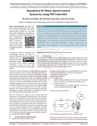
Project overview • The aim of the project is to develop a speed control system for DC motor using four-quadrant chopper. • Using four-quadrant chopper it is possible to demonstrate forward &reverse motoring and braking. • The speed of DC motor is directly proportional to armature voltage and inversely proportional to flux. • By maintaining the flux constant, the speed can be varied by varying the armature voltage. • The direction of rotation is reversed by reversing armature voltage.
Contd.. • In this project, we use a small FHP (Fractional Horse Power) DC motor whose field comprises of a permanent magnet. • The armature of that is excited by a variable dc supply obtained from four-quadrant chopper. • The system is provided with various control keys, such as START, STOP, FORWARD, REVERSE, FORWARD BRAKE, and REVERSE BRAKE. • Using these keys, the user can set the motor to run in any one of the following modes, namely Forward motoring, Reverse motoring, Forward braking and reverse braking. The speed can be varied by varying the voltage given to the PWM converter (using potentiometer).
FOUR QUADRANT OPERATION OF DC MOTOR • DC. Motor Equation
555 TIMER • The 555 Timer IC is an integrated circuit (chip) implementing a variety of timer and multivibrator applications. • The original name was the SE555 (metal can)/NE555 (plastic DIP) and the part was described as "The IC Time Machine". • Depending on the manufacturer, the standard 555 package includes over 20 transistors, 2 diodes and 15 resistorson a silicon chip installed in an 8-pin mini dual-in-line package (DIP-8)
PIN DIAGRAM OF 555 • The 555 timer IC is a simple 8 pin DIL package IC. • It can: • be used as a monostable • be used as an astable • source or sink 100mA • use supply voltages of 5v to 15v • disrupt the power supply - use a decoupling • capacitor!
MOTOR driver L293D • L293D is a dual H-bridge motor driver integrated circuit (IC). • Motor drivers act as current amplifiers since they take a low-current control signal and provide a higher-current signal. • This higher current signal is used to drive the motors. • L293D contains two inbuilt H-bridge driver circuits. In its common mode of operation, two DC motors can be driven simultaneously, both in forward and reverse direction.
Operation of motor driver • L293D has 2 set of arrangements where one set has input 1, input 2, output 1 and output 2 and other set has input 3, input 4, output 3 and output 4, according to block diagram if pin no 2 & 7 are high then pin no 3 & 6 are also high. • If enable 1 and pin number 2 are high leaving pin number 7 as low then the motor rotates in forward direction. • If enable 2 and pin number 10 are high leaving pin number 15 as low then the motor rotates in forward direction.
Contd.. • If enable 1 and pin number 2 are low leaving pin number 7 as high then the motor rotates in reverse direction. • If enable 2 and pin number 15 are high leaving pin number 10 as low then the motor rotates in forward direction.
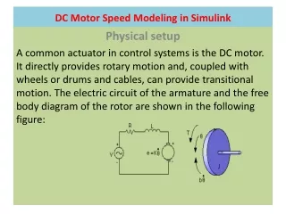
DC- MOTOR • A DC motor is an electric motor that runs on direct current (DC) electricity. In any electric motor, operation is based on simple electromagnetism. • A simple 2-pole DC electric motor (here red represents a magnet or winding with a "North" polarization, while green represents a magnet or winding with a "South" polarization). • Every DC motor has six basic parts -- axle, rotor (a.k.a., armature), stator, commutator, field magnet(s), and brushes.