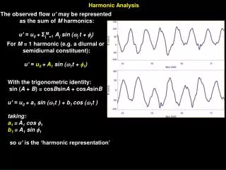
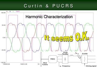
Harmonic Characterization
Harmonic Characterization. It seems O.K. Harmonic Characterization. Table of Contents. Brazil PUCRS Introduction Objectives Power Quality Harmonic Characterization The Harmonic Mitigation Schemes. The Harmonic Mitigation Schemes. Passive Harmonic Trap Filters (HTF)

Harmonic Characterization
E N D
Presentation Transcript
Harmonic Characterization It seems O.K.
Table of Contents • Brazil • PUCRS • Introduction • Objectives • Power Quality • Harmonic Characterization • The Harmonic Mitigation Schemes
The Harmonic Mitigation Schemes • Passive Harmonic Trap Filters (HTF) • Single-Switch Three-Phase Boost Rectifier • Three-Phase Boost type PWM Rectifier (AC-DC converter) Objectives • Active Power Filter
Using HTF for the 5th and 7th harmonic PMSG output current
Using HTF for the 5th and 7th harmonic PMSG output voltage
Table of Contents • Brazil • PUCRS • Introduction • Objectives • Power Quality • Harmonic Characterization • The Harmonic Mitigation Schemes • Power Losses
Power Losses • PMSG losses • Bridge Rectifier Losses • Harmonic Trap Filter Losses • Semiconductor Losses • Mechanical losses
Conclusions • In this work three well-known harmonic mitigation solutions were applied to PMSG WECS AC to DC conversion. They were the HTF, the PFC and the PWM. Harmonic trap filters are easily implemented by passive components but they are normally implemented with bulk components.
Conclusions • Notwithstanding the HTF had presented the good THD results they are not the best solution once they are a matched solution for a specific operation point (wind speed and output power). The losses study also has demonstrated that the PMSG efficiency (η) remains practically constant and the system η is the lowest when the HTF are used.
Conclusions • For these reasons, it is not a recommended way out to obtain harmonic mitigation on PMSG WECS. On the other hand, the single-switch three-phase boost rectifier has presented encouraged results. Such as: low current and voltage THD, simple power topology and control circuit, can work in all wind conditions and presents a real reduction of the PMSG total losses.
Conclusions • Which allow expecting an increasing in the PMSG lifetime without reduction of the power capability. The main drawbacks of this topology are a) the conduction losses in the BR diodes and switch Q1 since the high RMS current value caused by the DCM operation and b) the high output voltage 1 kV. Both problems could be minimized using proper diodes and switch like IGBT.
Conclusions • With the actual technology these problems could be easily solved. The PWM rectifier was studied once if this complex converter is possible to obtain ideal PF and THD. But the losses study has show results very closed to that obtained with the Single Switch Boost Converter. The main advantage is that with this converter is possible to work with output voltages around 600V in spite of 1000V.
THANK YOU • It was a pleasure be here I have enjoy the last six months as the bets in work life. • Special thanks to: Professor Syed Islam and all staff members. • I hope see you again here or in BRAZIL.