HARMONIC MITIGATION
HARMONIC MITIGATION. Installation of Mirus harmonic filters in TPS fields Prepared by Ahmed BOUJELBEN Electrical & Instrumentation Engineer Thyna Petroleum Services 7, Avenue Abderahmen EL GHAFIKI BP. 069 - 3069 Sfax Hached SFAX TUNISIA. Objectives.

HARMONIC MITIGATION
E N D
Presentation Transcript
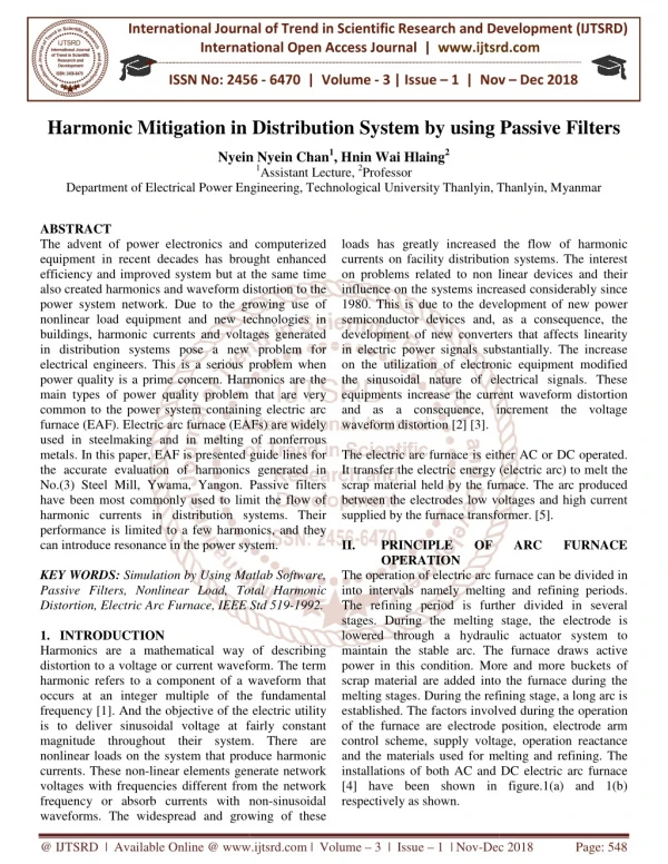
HARMONIC MITIGATION Installation of Mirus harmonic filters in TPS fields Prepared by Ahmed BOUJELBEN Electrical & Instrumentation Engineer Thyna Petroleum Services 7, Avenue Abderahmen EL GHAFIKI BP. 069 - 3069 Sfax Hached SFAX TUNISIA
Objectives • Reduce voltage and current harmonic distortion • Reduce Energy losses • Protect electrical equipment against the harmful effects of • harmonics • Avoid failure of equipment ( VFDs, motors, etc.) and • especially on offshore fields (Generator, battery charge, …). • Reduce maintenance cost • Realize energy saving
Abstract • Electric drives, both DC SCR and AC variable frequency drives (VFDs), are commonplace on drilling rigs and offshore installations. • Their operation can significantly degrade the quality of electric power, resulting in loss of operational capability, equipment failure with subsequent down-time in addition to presenting safety concerns. • Marine classification bodies have rules to limit harmonic voltage distortion but these are rarely policed. • The quality and security of electric power are absolutely crucial to the operational integrity of any drilling rig or offshore installation, irrespective of type or class. • Any failure or malfunction of equipment due to poor power quality can result in severe or disastrous consequences.
- • Power Quality Offshore is often taken for granted • Poor Power Quality on drilling rigs is due to the use of large AC and DC adjustable speed drives • Poor Power Quality results in: - Lost production - Equipment disruption and failure - Safety concerns
- ‘Harmonics’, a serious and growing problem worldwide, are due to conventional power conversion technologies (e.g. AC to DC conversion) which draw non-sinusoidal currents which interact with the system impedance(s) to produce voltage distortion up to the highest transmission levels. - Most countries have national standards (or adopt international standards such as the North American IEEE 519 (1992) in order to protect their electricity networks from excessive harmonic ‘pollution’ exported into the network by consumers. - In some parts of London it is now very difficult to get approval for large non-linear loads such AC variable frequency drives due to the Uthd (total harmonic voltage distortion) being very close to the limits set by Engineering Recommendation G5/4-1 (2001); the UK’s Electricity Associations ‘rules’ for harmonics.
Adjustable speed drives have many applications in the offshore sector • including main propulsion, thrusters, ‘drilling packages’ (i.e. mud • pumps , draw-work and top drives), compressors, fans, pumps • (especially electrical submersible types), leg racking drives on jack-up • rigs, cranes, etc. • For installations which rely on generator derived power (i.e. the vast • majority of drilling rigs) the resulting harmonic voltage distortion can • be up to 3 to 4 times that of transformer based power supplies of the • same given adjustable speed drive load. • - This is due largely to difference in source impedance between • transformers (e.g. 5-6%) and generators (e.g. 12-25%)
The numerous negative effects of harmonics are widely acknowledged that they generally fall into two basic categories : Excessive heating caused by additional RI² losses, skin effect et al in cables and in equipment (e.g. generators, transformers, motors, etc). Voltage distortion due to the harmonic currents ability to produce voltage drops in the various feeder impedances and leakage inductances of the system. In addition, line notching due to DC SCR drives can also be problematic. Consequently, marine classification societies and other bodies have rules and recommendations to limit the harmonic voltage distortion to 5% Uthd (total harmonic voltage distortion).
The result is a considerable number of installations have significantly more harmonic voltage distortion than permitted. It is not uncommon to measure up to FIVE to SIX times the permitted limit on some installations Any failure or malfunction of equipment due to poor power quality can result in loss of production or an incident with possible severe or disastrous consequences. The problem has been further compounded by offshore Health & Safety bodies across the world not policing the high levels of voltage distortion either; instead this is currently left to the oil companies to police themselves
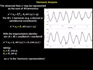
Quick Harmonic Refresher An ‘ideal’ single phase current and voltage waveforms associated with linear Typical current waveform of a computer switched mode power supply (SMPS) unit (and a single phase AC variable frequency drive (VFD). Fig 1 – Single phase linear load voltage and current waveforms Fig2-Single phase non-linear waveforms for computer or VFD
When all harmonic voltages and currents are added to the fundamental a waveform known as a ‘complex wave’ is formed
Fourier componentsAn example of complex wave consisting of the fundamental (1st harmonic) + 5th harmonic + 7thharmonic is illustrated as follows Complex wave Most VFD’s incorporate a 3-phase, 6-pulse diode bridge rectifier which generates current harmonics in the 5th, 7th, 11th, 13th, etc……. 5th harmoniccurrentis 250 Hz (5 x 50 Hz) 7th harmoniccurrentis 350 Hz (7 x 50 Hz) 11th harmoniccurrentis550 Hz (11 x 50 Hz)
Harmonic Spectrum and Current Waveform Single - phase loads Three- phase loads
The effects of harmonics ● Voltage distortion: - Excessive temperature rise in motors, cables - Electrical noises - Sensitive electronic equipment malfunction ● Increase in the apparent power and over-sizing of sources (UPS, Genset, etc.), capacitors, cables... - Derating of electrical equipment or over-sizing - Accelerated ageing of equipment ● Flow of current in the neutral conductor and consequently in the PEN: - Excessive temperature rise in transformer - Tripping of circuit breakers
The additional heating due to harmonics degrades optimaloperation because equipment can run at a higher temperature than designed. If a cable or a motor stator winding gets too hot as a result of harmonics, insulation can melt. Failure is usually the result; in extreme cases FIRES can occur. In hazardous areas, overheating of explosion motors can create a source of ignition with potentially catastrophic consequences. If voltages are distorted due to harmonics then that too can cause other equipment to MALFUNCTION. These are the key reasons why harmonics are Not to be ignored !!!
Harmonic Distortion THD (Total Harmonic Distortion) for currents, and voltages is one popular measure of Power Quality The THD of a voltage or current waveform is really a ratio of power dissipation due to harmonics, to power dissipation due to the fundamental This ratio allows one to predict how much “hotter” (i.e the temperature rise) the wiring or equipment will run, compared to the rated nameplate “design” temperature
Examples of equipment draw harmonic currents from the networkEssentially, the list (which is not exhaustive) is based mainly on equipment which converts AC power to DC power for internal use and includes the following : Single phase loads: • Computers • Printers • TVs • Fax machines • Lighting dimmers • Microwave ovens • Fluorescent light ballasts • Medical equipment • Ultrasonic equipment • AC and DC variable speed drives Three phase loads: • AC variable frequency drives • DC drives • UPS systems • Induction furnaces • Process and other rectifiers • Medical equipment
Main problems associated with poor power quality: • - Excessive harmonic voltage distortion • - Line notching (SCR drives) • - Voltage spikes attributed to SCR drives • These are all traditional ‘harmonics problems’.
Harmonic voltage distortion . During the conversion process from AC to DC, both DC SCR drives and from AC VFDs draw unwanted harmonic currents which are multiples of the supply frequency (e.g. 5th harmonic current is 5 x 50Hz = 250Hz) are drawn from the source. The individual harmonic currents then interact with the system impedance at their respective frequencies to produce voltage distortion at those frequencies.
HARMONIC VOLTAGE DISTORSIONMost conventional adjustable speed drives fed with sinusoidal voltages draw non-sinusoidal or ‘non linear’ current Example of line voltages distorted by AC VFDs (8.8% Uthd) . This Figure illustrates an example line voltages distorted due to excessive harmonics currents
Harmonic voltage distorsionExample of 3 x 800HP DC drives voltage waveforms - Uthd 12.2%
AC Variable Frequency Drives (VFDs)VFDs are increasingly popular on drilling rigs/ships Simplified 6 pulse AC VFD schematic
Both AC and DC adjustable speed drives draw nonlinear current but AC variable frequency drives (VFDs) tend to produce higher levels of harmonic voltage distortion The nonlinear phase currents drawn by a 1500HP/1100kW VFD at moderate load
DC SCR drives DC SCR drives are not as complex as VFDs and are essentially sophisticated DC voltage controllers where the output voltage largely determines the DC motor speed whilst the output DC current determines the motor torqueDC SCR drives draw nonlinear current:
Serious Cause for Concern – high order harmonics - The figure shows the Uthd (total harmonic voltage distortion) captured instantaneously on a 690V drilling package with a DC SCR drilling package. - The average Uthd was 25.61% of which 19.3% was >21st harmonic due mainly to large number of 24 pulse VFDs for submersible pumps connected to MV supplies. - The recommended limit for harmonic voltage for the installation was 5%.
Serious Cause for Concern – high order harmonicsWhy Cause for Concern ?
Common types of harmonic mitigation 1- Passive Wide Spectrum Filters Over the last 5-6 years the passive ‘wide spectrum filter’ has gained popularity within the drilling and marine sectors. The filter is connected in series with the drive load(s). These devices have been installed in sizes to 3500HP/2650kW for both AC VFD and for DC drives and are now being developed for MV (i.e. medium voltage) VFDs. Fig shows 2 x 2300HP/1800kW D type (AC) wide spectrum filters : These units were connected to an AC VFD common DC bus system for three mud pumps. The Uthd was reduced to below 5% to meet requirements.
2- Active Harmonic Filter Parallel active filters are similar in technology to VFDs, they treat the harmonic currents (not the main rms current), which are typically around 30-40% of the full rms source current value. In a correctly dimensioned system the vast majority of the harmonic currents are drawn from the active filter and only the fundamental current is drawn from the generator or transformer Parallel active filter current waveforms
The effects (Ithd and Uthd) of 1500A of harmonic filters on a DC SCRdrilling package comprising 3x 900HP/630kW DC SCR drives retrofitted with 3% AC line reactors. Uthd on 3 x 600kW DC drives without/with/without harmonic filter. Uthd reduced from 11.2% to 3.2%. Ithd on 3 x 630kW DC SCR drives without/with/without Harmonic Filter. Ithd reduced from 35% to 3.7% Without harmonic filter With Harmonic filter With Harmonic filter
Line notching‘Line notching’ is usually associated with phase controlled semi-conductors such as SCRs(i.e. silicon controlled rectifiers or thyristors). Line notching can also be seen in high powered AC drives with diode rectifiers under certaincircumstances. Severe line notching on due to fully controlled SCR rectifiers on DC drilling package
Reduction of line notching 3 x 900HP DC drives voltage waveforms with 3% AC line reactors only Without Harmonic filter 3 x 900HP DC drives voltage waveforms with active harmonic filter and 3% AC line reactors. With harmonic filter
Voltage spikes Fig. illustrates a typical example of voltage spikes Damage due to voltage spikes on small to medium powered VFDs. Failure of rectifier devices and DC bus capacitors
Attenuation of voltage spikesUsing Wide Spectrum FilterThe input (upper trace) and output (lower trace) to/from a wide spectrum filter on a DC drilling package. Fig above illustrates how effect this wide spectrum filter type of solution can be. These are now being promoted throughout the drilling industry.
Wide Spectrum FilterThe Lineator(Advanced UniversalHarmonicFilter) Treats all major harmonics generated by Variable Speed Drives and other 3-phase rectifier loads (5th, 7th, 11th, 13th …) A relatively low cost and very effective solution is to install a suitable wide spectrum harmonic filter between the sensitive VFDs and the voltage notches. The wide spectrum filter treats the harmonic currents drawn from the supply as design but also acts as a ‘blocking filter’ and effectively isolates the VFDs from overvoltage and other disturbances Compatible with engine generators
MirusLineator Passive filters solution was selected for all TPS fields The Lineator™ (AUHF) Advanced Universal Harmonic Filter • The LINEATOR ™ is a purely passive device consisting of a revolutionary new inductor combined with a relatively small capacitor bank. • It's innovative design achieves cancellation of all the major harmonic currents (including AM Band RFI) generated by VSD's and other similar 3- phase, 6-pulse rectifier loads. • The resulting Ithdis reduced to < 8% and often as low as 5%.
Features • Treats all major harmonics generated by Variable Speed Drives and other 3-phase rectifier loads (5th, 7th, 11th, 13th …) • Exceeds 18-pulse performance in a smaller footprint, at lower cost and without sacrificing energy efficiency • Easily applied to input of a single VSD • No need to phase shift against other VSD’s • Will meet IEEE 519 standard for both current and voltage distortion • Input current demand distortion < 8% over entire operating range • Power factor 0.98 lagging to 0.95 leading over the normal operating range • Compatible with engine generators since capacitive reactance is < 15% of rated kVA even under light loads • Will not resonate with other power system components • Will not be overloaded by other line side harmonic sources • Suppresses over voltages caused by capacitor switching and other fast changing loads • Eliminates need for drive isolation transformers, AC line reactors and DC link chokes • Removal of harmonics improves overall system power factor • Saves energy by reducing upstream harmonic losses • Reduces DC bus ripple and increases ride-through capability of the load
. TPS experience As a first step: • TPS selected 4 sites • Mirus was selected as suitable filter technology for all TPS locations • TPS has purchased and installed 4 Lineator filters (2 filters onshore + 2 filters offshore) • Acceptable performances was achieved despite of using filter at light load, Performance will be presented As second step: Mirus Lineator filters solution was generalized for all TPS fields.
Waveforms Lineator (Advanced UniversalHarmonicFilter) Before filter installation After filter installation
BEFORE Harmonic Mitigation:Waveforms and harmonics Spectrums Uthd = 6,3% Ithd = 72,2 % Current Voltage
AFTER Harmonic Mitigation:Formes des ondes et spectres harmoniques Uthd = 2,2 % Ithd = 7,2 % Voltage Current
AFTER MITIGATIONSummary Compliance with IEEE std 519 – (1992)
RESULTS • Reduction of voltage and current harmonic distortion • Reduction of Energy losses • 20% KVA Reduction & 80% KVAR Reduction • Realization of saving energy • Protection of electrical equipment against the harmful effects of harmonics • Reduction of maintenance cost
Investing in power quality will improve both your operations and profits Contact for advice or assistance in Tunisia Green Planet Amélioration de la qualité de puissance et traitement des courants harmoniques Résidence Dorret Carthage - Les Jardins de Carthage Tél : 22 323 499 / 53 715 500 Fax : 71 265 140 Email : greenplanet@planet.tn Contact : Fethi Ben Bouzid