School of Engineering
180 likes | 365 Vues
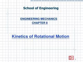
School of Engineering. ENGINEERING MECHANICS CHAPTER 8. Kinetics of Rotational Motion. 8.1 Brief Kinetics of rotational motion is the study of rotational motion caused by external torque. 8.2 Newton’s second law for Rotational Motion It can be written in mathematical form as:

School of Engineering
E N D
Presentation Transcript
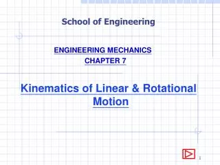
School of Engineering ENGINEERING MECHANICS CHAPTER 8 Kinetics of Rotational Motion
8.1 Brief Kinetics of rotational motion is the study of rotational motion caused by external torque. 8.2 Newton’s second law for Rotational Motion It can be written in mathematical form as: = I for a single torque = I for several torque where is the torque (Nm – rotating shaft) I is the moment of inertia (kgm2) is the acceleration (rad/s2) (Note:- I = mk2, where m is the mass and k is the radius of gyration.)
8.3 Free Body diagram • We note that since the motion is caused by torque acting on the body, the first step would be to show all the torque acting on it. This is set out in the form of a free body diagram indicating clearly all external torque. A free body diagram is a diagram showing only the body and the torque acting directly on it. • 8.4 Sign Convention • We are interested to determine the motion of the body hence we choose the direction of the resulting rotation as the positive direction. However, any direction can be selected as positive but this must be strictly adhered to throughout the analysis.
Example 8.1 A rotor with a mass moment of inertia of 6 kgm2 about its center of mass has a torque of 90 Nm applied to it. Determine the angular acceleration of the rotor. 90 Nm Solution: By Newton’s law, = I 90 = 6 = 15 rad/s2
Flywheel 5kg Spindle 20kg Example 8.2 The flywheel has a mass of 5 kg and a radius of gyration of 200 mm. The 20 kg mass, attached to a rope wrapped around the spindle of diameter 30 mm, is allowed to fall from rest. Calculate the angular acceleration of the wheel and the acceleration of the 20 kg mass.
dia =30 mm T T 20g Solution: For the flywheel, I = mk2 = 5 x 0.22 = 0.2 kgm2 Torque on flywheel, = T x 0.015 Nm = I T x 0.015 = 0.2 T = (0.2 / 0.015) ---------- (1) For the mass, F = ma 20g – T = 20a ----------- (2) a = r = a / 0.015 ------------- (3)
From (1) & (3), T = (0.2 / 0.015) x (a / 0.015) = 0.2a / 0.0152 Sub into (2), 20g – 0.2a / 0.0152 = 20a a = 0.216 m/s2 From (3), = 0.216 / 0.015 = 14.4 rad/s2
Winch 300kg Example 8.3 A power-driven winch is used to raise a mass of 300 kg with an acceleration of 2 m/s2. The winch drum is 0.5 m in diameter and has a mass moment of inertia about its center of 8 kgm2. What torque must be applied to the winch drum?
T T a 300g For the mass, F = ma T - 300g = 300 x 2 T = 3543 N • For the drum, • a = r • 2 = 0.25 = 8 rad/s2 • = I • a - 3543 x 0.25 = 8 x 8 • a = 950 Nm
Example 8.4 A compound pulley having a mass of 4 kg and a radius of gyration 0.28 m, is connected to two masses A and B as shown. Assuming no axle friction, determine the acceleration of the masses. rB = 0.3 m rA = 0.1 m A 10kg B 20kg
TA TB TB 20g TA 10g I = mk2 = 4 x 0.282 = 0.3136 kgm2 Assume acceleration clockwise: = I TB x 0.3 – TA x 0.1 = 0.3136 --------------- (1)
TA TB TB 20g TA 10g For pulley, = aA / rA = aB / rB ----------- (4) For block A, F = ma TA – 10g = 10 aA ---------- (2) For block B, F = ma 20g – TB = 20 aB -------- (3)
TA TB TB 20g TA 10g Sub (4) into (2), TA – 10g = 10 x 0.1 TA = + 10g --------------- (5) Sub (4) into (3), 20g – TB = 20 x 0.3 TB = - 6 + 20g --------------- (6)
TA TB TB 20g TA 10g Sub (5) & (6) into (1), (- 6 + 20g) x 0.3 – ( + 10g) x 0.1 = 0.3136 = 22.154 rad/s2 aA = rA= 0.1 x 22.154 = 2.215 m/s2 aB = rB = 0.3 x 22.154 = 6.646 m/s2
Pulley Winch Block A 200 kg 60 Example 8.5 A power driven winch can exert a torque of 1200 Nm. It has a drum of 80 cm diameter and a mass moment of inertia of 30 kgm2. It is used to raise block A of mass 200 kg up the slope as shown in the figure. The coefficient of friction between block A and the slope is 0.3. Assume the pulley is frictionless. • Draw the free body diagrams of the winch and block A. • Determine the acceleration of block A and the tension in the cable.
T = 1200 Nm T 200g Winch a F1 N1 60 Block A Block A: For the direction perpendicular to the slope, Fy = 0 N1 – 200gcos60 = 0 N1 = 981 F1 = N1 = 0.3 x 981 = 294.3 N
T = 1200 Nm 200g T Winch a F1 N1 60 Block A For the direction up the slope, Fx = ma T – 294.3 – 200gsin60 = 200a T = 1993.44 + 200a ---------- (1) For the drum, a = r = (a / 0.4)
T = 1200 Nm 200g T Winch a F1 N1 60 Block A For the anti-clockwise direction, = I 1200 – 0.4T = 30 x (a / 0.4) 1200 – 0.4T – 75a = 0 --------- (2) Substitute (1) into (2) 1200 – 0.4 (1993.44 + 200a) – 75a = 0 a = 2.6 m/s2 Sub. into (1) T = 1993.44 + 200 x 2.6 = 2513.44 N End of Chapter 8