Download
1 / 31
310 likes | 325 Vues
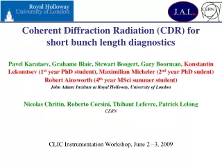
Role of Electromagnetic Radiation in Charged Particle Bunch Length Diagnostics. JAI@RHUL. Pavel Karataev John Adams Institute for Accelerator Science at Royal Holloway, University of London. 1) Introduction: Incoherent and coherent emission Radiation spectrum

E N D
Role of Electromagnetic Radiation in Charged Particle Bunch Length Diagnostics JAI@RHUL Pavel Karataev John Adams Institute for Accelerator Science at Royal Holloway, University of London karataev@pp.rhul.ac.uk
1) Introduction: • Incoherent and coherent emission • Radiation spectrum • Longitudinal bunch form factor 2) Radiation mechanisms: • Synchrotron radiation • Polarization Bremsstrahlung • Transition radiation • Diffraction radiation • Smith-Purcell radiation 3) Kramers-Kronig method for longitudinal profile reconstruction 4) Summary Lecture content
Radiation spectrum S() – radiation spectrum Se() – single electron spectrum N – number of electrons in a bunch F() – longitudinal bunch form factor (s) – Longitudinal particle distribution in a bunch
Gaussian beam Assume N = 1010 e/bunch Coherent radiation appears when the bunch length is comparable to or shorter than the emitted radiation wavelength
Example 1: Two Gaussian beams Assume we have a main bunch with s = 2mm (6.7ps) andN = 1010 and a microbunch in it with sm = 0.2mm (0.67ps) and Nm = 106.
Example 1: Two Gaussian beams Assume we have a main bunch with s = 2mm (6.7fs) andN = 1010 and a microbunch in it with sm = 0.2mm (0.67fs) and Nm = 106.
Radiation spectrum • S() – radiation spectrum (can be measured in the experiment) • N – number of electrons on the bunch (known from the experiment) • F() – bunch form function (measurement purpose) • Se() – single electron spectrum (should be known)
Synchrotron radiation Synchrotron radiation appears when a charged particle beam is bent in a magnetic field is the charged particle Lorentz-factor is the bending radius
Synchrotron radiation Advantages for diagnostics: - in circular accelerators it is just generated - in linear accelerators it might exist in magnet chicanes and bunch compressors - no need for any special insertion devices Disadvantages for diagnostics: - very difficult to predict (spectrum might be distorted while propagating through the vacuum chamber) - impossible to separate from background (e.g. wakefield radiation)
Example 2: Microbinch Instabilities in Storage Rings M. Venturini, et al., PR ST-AB 8, 014202 (2005)
Example 2: Microbinch Instabilities in Diamond LS 1.9 mA Schottky Barrier Diode was used as a detector sensitive to 3.33 – 5mm radiation wavelength 3.0 mA 5.2 mA
Polarization Bremsstrahlung A charged particle moving in condensed matter approaches the atom polarizing it
Polarization Bremsstrahlung A charged particle moving in condensed matter approaches the atom polarizing it wikipedia i) Radiation is defined by the electrons of medium ii) The energy loss due to the process is so small that the particle is assumed to be moving rectilinearly and with constant velocity iii) There is no dependence on the particle mass (it depends on particle energy and its charge)
Polarization Bremsstrahlung • Cherenkov radiation • Transition radiation • Diffraction radiation • Smith-Purcell radiation • Parametric X-ray radiation in crystals
Polarization Bremsstrahlung • Cherenkov radiation • Transition radiation • Diffraction radiation • Smith-Purcell radiation • Parametric X-ray radiation in crystals
It appears when a charged particle crosses a boundary between two media with different dielectric properties Transition Radiation
Transition Radiation Advantages for diagnostics: - Instantaneous emission - Large emission angles - High intensity, i.e. single shot measurements are possible - Spectrum can be predicted with proper accuracy Disadvantages for diagnostics: - Invasive mechanism (can not be used in rings) - High brightness beam might destroy the target - The target can change the beam parameters
Single particle distribution at the target surface (Half Width at Half Maximum, HWHM is a couple of wavelengths) Example 3: OTR beam profile monitor Measuring the incoherent part of radiation spectrum we do not have to care about single particle distribution as long as the transverse beam size is much larger it M. Castellano and V. Verzilov, Phys. Rev. ST-AB 1, 062801 (1998)
Example 3: SLAC OTR monitor at KEK-ATF Very high resolution for an OTR monitor (~2m) predicted by the theory but only ~5.5m spot was actually measured.
Example 3: Linac Coherent Light Source 200fs (0.06mm) 25fs (0.0075mm) H. Loos, et al., SLAC-pub-13395
Example 3: OTR spectrum at LCLS • The form of the coherent spectrum fluctuates from shot to short • Existence of spikes in the spectrum suggests that there are a few microbunches in the longitudinal particle distribution • The coherent part of the OTR intensity could be much higher than the incoherent one H. Loos, et al., SLAC-pub-13395
It appears when a charged particle moves in the vicinity of a medium Diffraction Radiation • - observation wavelength = E/mc2 – Lorentz - factor Impact parameter, h, – the shortest distance between the target and the particle trajectory
Non-invasive method (no beam perturbation or target destruction) • Instantaneous emission (quick measurements) • Single shot measurements (no additional error from shot-by-shot instabilities) • Large emission angles (0 ~ 1800) (good background conditions) • Single electron spectrum is predictable Diffraction Radiation Advantages
Coherent Diffraction Radiation experiment at CTF3 in CERN • For our setup at CTF3, h ≈ 15 mm ≤ = 1175 for = 235 and = 5mm; • SR background will be blocked by the first target; • Ultra-fast Schottky Barrier Diode detector (time response <250ps) is used
Vacuum manipulator for target rotation and translation CDR setup at CTF3 CRM.MTV0210 for target reference position CDR target within six-way cross CR.SVBPM0195 (not shown in picture) for beam position and charge readings SBD detector connected to DAQ
CDR signal • Current was measured with a BPM • Signal acquired by a digitizer (4Gs/s) • 3GHz bunch sequence rate (0.33ns) • Train length is 200ns (~600 bunches)
Emission from blazed grating Smith-Purcell Radiation e- beam blazed grating • Beam test at SLAC End station A (28.5 GeV) V. Blackmore, G. Doucas, et al., Physical Review ST-AB 12, 032803 (2009)
Smith-Purcell Radiation Advantages: • Non-invasive method • Instantaneous emission • Single shot measurements • Large emission angles (0 ~ 1800) • Disadvantages: • Smith-Purcell theory is not as advanced as for DR. Prediction of a single electron spectrum is a challenging task, but not impossible
Kramers - Kronig method Here: c is the speed of light; s is the longitudinal coordinate; () is the initial phase.
Tools based on coherent radiation are certainly useful for longitudinal charged particle beam diagnostics in modern and future accelerator machines as: • it does not have any theoretical resolution limit • it gives information about longitudinal dimensions and structure • There is a set of problems which still need to be resolved: • Coherent radiation backgrounds; • Precise prediction of a single electron spectrum; • Precise extrapolation method for phase reconstruction; • The method should be robust and simple in use; • The hardware should be relatively inexpensive. Summary • Modern accelerators have a lot of surprises which need to be identified and resolved