Contact Mechanics
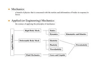
Contact Mechanics. Asperity. SEM Image of Early Northeastern University MEMS Microswitch. Asperities. SEM of Current NU Microswitch. Nominal Surface. Two Scales of the Contact. Contact Bump (larger, micro-scale) Asperities (smaller, nano-scale). Depth at center

Contact Mechanics
E N D
Presentation Transcript
Asperity SEM Image of Early Northeastern University MEMS Microswitch
Asperities SEM of Current NU Microswitch
Nominal Surface Two Scales of the Contact • Contact Bump (larger, micro-scale) • Asperities (smaller, nano-scale)
Depth at center Curvature in contact region p(r) p0 Pressure Profile r a Resultant Force Basics of Hertz Contact The pressure distribution: produces a parabolic depression on the surface of an elastic body.
rigid R r Basics of Hertz Contact Elasticity problem of a very “large” initially flat body indented by a rigid sphere. We have an elastic half-space with a spherical depression. But:
Basics of Hertz Contact • So the pressure distribution given by: gives a spherical depression and hence is the pressure for Hertz contact, i.e. for the indentation of a flat elastic body by a rigid sphere with • But wait – that’s not all ! • Same pressure on a small circular region of a locallyspherical body will produce same change in curvature.
P E2,2 R2 Interference 2a E1,1 R1 Contact Radius Effective Young’s modulus Effective Radius of Curvature Hertz Contact Hertz Contact (1882)
Assumptions of Hertz • Contacting bodies are locally spherical • Contact radius << dimensions of the body • Linear elastic and isotropic material properties • Neglect friction • Neglect adhesion • Hertz developed this theory as a graduate student during his 1881 Christmas vacation • What will you do during your Christmas vacation ?????
Onset of Yielding • Yielding initiates below the surface when VM = Y. Fully Plastic (uncontained plastic flow) Elasto-Plastic (contained plastic flow) • With continued loading the plastic zone grows and reaches the surface • Eventually the pressure distribution is uniform, i.e. p=P/A=H (hardness) and the contact is called fully plastic (H 2.8Y).
Critical issues for profile transfer: Process Pressure Biased Power Gas Ratio Round Bump Fabrication Shipley 1818 Shipley 1818 The shape of the photo resist is transferred to the silicon by using SF6/O2/Ar ICP silicon etching process. Photo Resist Before Reflow Photo Resist After Reflow Silicon Bump Silicon Bump O2:SF6:Ar=20:10:25 O2:SF6:Ar=15:10:25
Evolution of Contacts After 10 cycles After 102 cycles After 103 cycles After 104 cycles
Elasto-Plastic Contacts (L. Kogut and I Etsion, Journal of Applied Mechanics, 2002, pp. 657-662) c, aC, PC are the critical interference, critical contact radius, and critical force respectively. i.e. the values of , a, P for the initiation of plastic yielding Curve-Fits for Elastic-Plastic Region Note when /c=110, then P/A=2.8Y
Fully Plastic Single Asperity Contacts(Hardness Indentation) • Contact pressure is uniform and equal to the hardness (H) • Area varies linearly with force A=P/H • Area is linear in the interference = a2/2R
Nanoindenters Hysitron Ubi® Hysitron Triboindenter®
Nanoindentation Test Indent Force vs. displacement
H0=0.58 GPa h*=1.60m Depth-Dependent Hardness Data from Nix & Gao, JMPS, Vol. 46, pp. 411-425, 1998.
Mean of Asperity Summits Mean of Surface Surface Topography Standard Deviation of Surface Roughness Standard Deviation of Asperity Summits Scaling Issues – 2D, Multiscale, Fractals
Contact of Surfaces Flat and Rigid Surface d Reference Plane Mean of Asperity Summits Typical Contact
2a Typical Contact P Original shape Contact area R
z (z) Multi-Asperity Models(Greenwood and Williamson, 1966, Proceedings of the Royal Society of London, A295, pp. 300-319.) Assumptions • All asperities are spherical and have the same summit curvature. • The asperities have a statistical distribution of heights (Gaussian).
z (z) Multi-Asperity Models(Greenwood and Williamson, 1966, Proceedings of the Royal Society of London, A295, pp. 300-319.) Assumptions (cont’d) • Deformation is linear elastic and isotropic. • Asperities are uncoupled from each other. • Ignore bulk deformation.
Greenwood & Williamson Model • For a Gaussian distribution of asperity heights the contact area is almost linear in the normal force. • Elastic deformation is consistent with Coulomb friction i.e. A P, F A, hence F P, i.e. F = N • Many modifications have been made to the GW theory to include more effects for many effects not important. • Especially important is plastic deformation and adhesion.
Contacts With Adhesion(van der Waals Forces) • Surface forces important in MEMS due to scaling • Surface forces ~L2 or L; weight as L3 • Surface Forces/Weight ~ 1/L or 1/L2 • Consider going from cm to m • MEMS Switches can stick shut • Friction can cause “moving” parts to stick, i.e. “stiction” • Dry adhesion only at this point; meniscus forces later
Forces of Adhesion • Important in MEMS Due to Scaling • Characterized by the Surface Energy () and the Work of Adhesion () • For identical materials • Also characterized by an inter-atomic potential
1.5 Some inter-atomic potential, e.g. Lennard-Jones 1 Z0 0.5 TH Z s / s 0 -0.5 -1 0 1 2 3 Z/Z 0 Adhesion Theories (A simple point-of-view) For ultra-clean metals, the potential is more sharply peaked.
P R2 R1 P Two Rigid Spheres:Bradley Model Bradley, R.S., 1932, Philosophical Magazine, 13, pp. 853-862.
P P1 a a JKR ModelJohnson, K.L., Kendall, K., and Roberts, A.D., 1971, “Surface Energy and the Contact of Elastic Solids,” Proceedings of the Royal Society of London, A324, pp. 301-313. • Includes the effect of elastic deformation. • Treats the effect of adhesion as surface energy only. • Tensile (adhesive) stresses only in the contact area. • Neglects adhesive stresses in the separation zone.
Derivation of JKR Model Stored Elastic Energy Mechanical Potential Energy in the Applied Load Surface Energy Total Energy ET Equilibrium when
Deformed Profile of Contact Bodies P • JKR model • Stresses only remain compressive in the center. • Stresses aretensile at the edge of the contact area. • Stresses tend to infinityaround the contact area. P p(r) JKR a r a a JKR Model Pressure Profile p(r) • Hertz model Only compressive stresses can exist in the contact area. Hertz a r
JKR Model • When = 0, JKR equations revert to the Hertz equations. • Even under zero load (P = 0), there still exists a contact radius. • F has a minimum value to meet the equilibrium equation • i.e. the pull-off force.
p(r) Applied Force, Contact Radius & Vertical Approach a r DMT Model Derjaguin, B.V., Muller, V.M., Toporov, Y.P., 1975, J. Coll. Interf. Sci., 53, pp. 314-326. Muller, V.M., Derjaguin, B.V., Toporov, Y.P., 1983, Coll. and Surf., 7, pp. 251-259. DMT model • Tensile stresses exist outside the contact area. • Stress profile remains Hertzian inside the contact area.
DMT theory applies (stiff solids, small radius of curvature, weak energy of adhesion) JKR theory applies (compliant solids, large radius of curvature, large adhesion energy) JKR-DMT Transition Tabor Parameter: Recent papers suggest another model for DMT & large loads. J. A. Greenwood 2007, Tribol. Lett., 26 pp. 203–211 W. Jiunn-Jong, J. Phys. D: Appl. Phys. 41 (2008), 185301.
1.5 Maugis approximation 1 0.5 TH s / s 0 h0 -0.5 -1 0 1 2 3 Z/Z 0 Maugis Approximation where
1.5 JKR Maugis 1 0.5 Lennard-Jones TH s / s 0 DMT -0.5 -1 0 1 2 3 Z/Z 0 Adhesion of Spheres Tabor Parameter JKR valid for large DMT valid for small and TH are most important E. Barthel, 1998, J. Colloid Interface Sci., 200, pp. 7-18
Adhesion Map K.L. Johnson and J.A. Greenwood, J. of Colloid Interface Sci., 192, pp. 326-333, 1997
Multi-Asperity Models With Adhesion • Replace Hertz Contacts of GW Model with JKR Adhesive Contacts: Fuller, K.N.G., and Tabor, D., 1975, Proc. Royal Society of London,A345, pp. 327-342. • Replace Hertz Contacts of GW Model with DMT Adhesive Contacts: Maugis, D., 1996, J. Adhesion Science and Technology, 10, pp. 161-175. • Replace Hertz Contacts of GW Model with Maugis Adhesive Contacts: Morrow, C., Lovell, M., and Ning, X., 2003, J. of Physics D: Applied Physics, 36, pp. 534-540.
http://www.unitconversion.org/unit_converter/surface-tension-ex.htmlhttp://www.unitconversion.org/unit_converter/surface-tension-ex.html