Formula SAE Team Final Presentation 12/4/2013
360 likes | 781 Vues
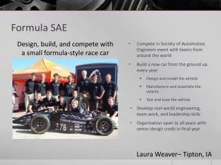
Formula SAE Team Final Presentation 12/4/2013. Frame Analysis Team Josh Carroll Lloyd Outten. Intake & Exhaust Team James Hogge Rebekah McNally Alisa Phillips Henos Woldegiorgis. Upright Team Lloyd Outten Joseph Perry Josh Carroll Taylor Watkins. Introduction to Formula SAE.

Formula SAE Team Final Presentation 12/4/2013
E N D
Presentation Transcript
Formula SAE TeamFinal Presentation12/4/2013 • Frame Analysis Team • Josh Carroll • Lloyd Outten • Intake & Exhaust Team • James Hogge • Rebekah McNally • Alisa Phillips • Henos Woldegiorgis • Upright Team • Lloyd Outten • Joseph Perry • Josh Carroll • Taylor Watkins
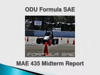
Introduction to Formula SAE • Design Competition for Collegiate students • Represent ODU’s Engineering Department • 8 part competition (8 Events)
[Car 106 Front Upright] [Car 106 Rear Upright] Uprights
Front Uprights • Good Design, but hard to machine. The integrated components would add excess machining time and cost • Retains the strength and low weight of original design while lowering machining cost. • Separated steering and brake brackets.
Front Upright Assembly Brake Bracket Upper A-Arm Connection Brake Caliper Connection Upper A-Arm Bracket Spec Sheet Material: 6061 Aluminum Total Assembly Weight. 2.45 lb. Total Assembly Volume: 25.80 in3 Weight by Part Main Upright 1.42 lb. Brake Bracket 0.44 lb. Upper A-Arm Bracket 0.12 lb. Spindle 0.33 lb. Steering Bracket 0.11 lb. Main Upright Steering Bracket Spindle Lower A-Arm Connection
Front Upright Stress Analysis Normal Loading Braking Force Steering Force Represents Maximum Braking Force Maximum Von Mises Stress: 46,929,128 N/m^2 Factor of Safety: 5.86 Represents Maximum Steering Force Maximum Von Mises Stress: 117,611,216 N/m^2 Factor of Safety: 2.34 Represents Weight of Car at maximum Turning Maximum Von Mises Stress: 46,152,184 N/m^2 Factor of Safety: 5.96
Rear Uprights Midterm Final Design Final Design Original Design • One solid piece • Heavy (2.51 lbs) • Requires optimization • One solid piece • Very light (1.64 lbs) • Difficult to machine • Sharp edges result in multiple stress concentrations • Three pieces • Upright • Two control arm mounts • Lighter than original (2.16 lbs) • Fewer corners mean fewer stress concentrations • Easier to machine
Rear Upright Assembly Upright Upright Specs Total Weight: 2.16 lbs Material: Al 6061-T6 Yield Strength: 31,183 psi (215 Mpa) Weight by Part: Upright: 2.02 lbs Mounts: 0.07 lbs e. Control Arm Mounts
Rear Upright Stress Analysis Load Transfer Cornering Full Simulation Lateral force on upright due to turning. Max von Mises Stress: 56.1 Mpa (8136.6 psi) Factor of Safety: 4.9 Maximum load transfer onto the upright due to acceleration. Max von Mises Stress: 14.3 Mpa (2059.5 psi) Factor of Safety: 19.29 Simulation of both the load transfer and lateral force applied to upright due to turning Max von Mises Stress: 57 Mpa (8267.2 psi) Factor of Safety: 4.82
Intake/Exhaust • Current Accomplishments: • Researched different intake styles and chose the most efficient style • Created and revised design in SolidWorks • Completed flow analysis • Ordered materials for intake
Research: Intake & Exhaust • Intake Research • Research determined that a spherical collector upright intake was the most efficient design • (1). The taper of the cone collector should be between 3-7 degrees • (2). Optimal runner length of 250-325mm • (3). 20 mm FSAE mandated restrictor • Exhaust Research • Typical stock exhaust uses small diameter crush bent pipe or mandrel bent pipe. • Crush bents are easier and cheaper to make however reduce the flow by 50%. • To produce the most power exhaust should have minimal restriction on the exact flow. • Components: 4 headers and silencer canister (muffler) (2) (3) (1)
Intake: Flow Analysis • Analysis • Bernoulli’s equation provides accurate pressure drop calculations • Air Flow velocites obtained by SolidWorks to check for choked flow • Flow rates can be calculated to compare the theoretical volumetric efficiency • Real world Flow Bench testing in the future to determine actual volumetric efficiency Choked Flow =1.4 (for air)
Intake: Flow Analysis • Analysis • FloXpress provides flow through one intake runner at a time • Testing in SolidWorks using the pressure drop calculations • Goal is to verify when restriction chokes engine air flow. • Choked flow only after 11000 RPM -Airflow through the intake at 9500 RPM -RPM at which max power was previously recorded -Airflow through the intake at 11000 RPM, when choke flow begins
Final Cost Report Total Estimated Cost $217.04
Future Plans: Fabrication -Runners made of pieced together pre-bent mandrel tube -Flanges laser cut by Bauer Compressor of Norfolk -Restriction turned from solid aluminum round -Collector rolled from flat aluminum sheet
Frame Analysis • Accomplishments • Finite Element Analysis • Patranand Nastran • 5 loading cases • CBAR (1D) Mat. Prop. • 4031 Annealed Steel • Various Diameters
Statically Loaded Case Factor of Safety: 4.17
Roll Over Case Factor of Safety: 4.0
Rolled Over (Upside Down) Case Factor of Safety: 17.6
Frontal Impact Case **Forces from Statically Loaded case also included in this analysis**
Frontal Impact Case Factor of Safety: .015
Side Impact Case **Forces from Statically Loaded case also included in this analysis** **Same Total Force Used from Frontal Impact**
Side Impact Case Factor of Safety: .016